Bolted Connection Design: AISC 360 Guide
Master bolted steel connection design: bolt grades, shear and bearing checks, tearout, block shear, and slip-critical vs bearing-type connections per AISC 360-22.
What is a bolted connection in steel structures?
A bolted connection transfers forces between steel members using high-strength bolts passing through aligned holes. It is the most common connection type in steel construction because bolts are fast to install, allow field adjustments, and can be inspected visually.
Every bolted connection must be designed so that no single failure mode — bolt shear, bearing, tearout, block shear, or net section rupture — is exceeded under factored loads. AISC 360-22 Chapter J provides the limit-state equations, and the designer's job is to identify the governing mode.
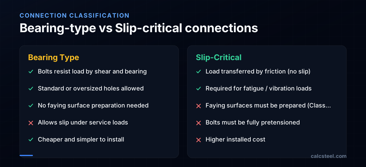
Bolted connections fall into two categories: - Bearing-type: Bolts transfer load through direct shear and bearing against the plate. Slip is allowed. This is the default for most connections. - Slip-critical: Bolts are pretensioned to clamp the plies together, and load is transferred by friction. Required when slip would cause misalignment, fatigue issues, or when oversized/slotted holes are used.
What bolt grades are used in structural steel connections?
Structural bolts are high-strength fasteners, not ordinary machine bolts. The two primary grades are:
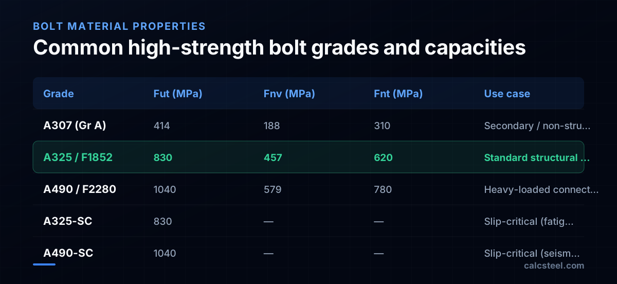
ASTM A325 (equivalent: ISO 8.8, ASTM F3125 Gr F1852) - Ultimate tensile strength: F_ut = 830 MPa (120 ksi) - Nominal shear strength (threads excluded): F_nv = 457 MPa - Nominal tensile strength: F_nt = 620 MPa - Available in diameters M16 to M36 - Most common bolt in US structural practice
ASTM A490 (equivalent: ISO 10.9, ASTM F3125 Gr F2280) - Ultimate tensile strength: F_ut = 1040 MPa (150 ksi) - Nominal shear strength (threads excluded): F_nv = 579 MPa - Nominal tensile strength: F_nt = 780 MPa - Used when A325 bolts are insufficient or fewer bolts are desired - Not permitted for galvanized connections (hydrogen embrittlement risk)
The -N suffix means threads are in the shear plane (reduces shear capacity to 80% of the -X value). Always specify -N unless you can guarantee threads are excluded from the shear plane, which is difficult in practice.
> CalcSteel tip: The connection editor automatically selects bolt grade and diameter based on demand forces, and checks every failure mode in one pass.
How do you check bolt shear strength per AISC 360?
Bolt shear is usually the first check. The design shear strength per bolt is:
φR_n = φ × F_nv × A_b
Where: - φ = 0.75 (LRFD) or Ω = 2.00 (ASD) - F_nv = nominal shear stress (depends on grade and thread condition) - A_b = nominal bolt area = π d² / 4
Worked example — 3×M20 A325-N bolts in single shear
- d = 20 mm → A_b = π(20)²/4 = 314.2 mm²
- F_nv = 457 MPa (A325, threads in shear plane → use F_nv directly per AISC Table J3.2)
- Per bolt: φR_n = 0.75 × 457 × 314.2 × 10⁻³ = 107.7 kN
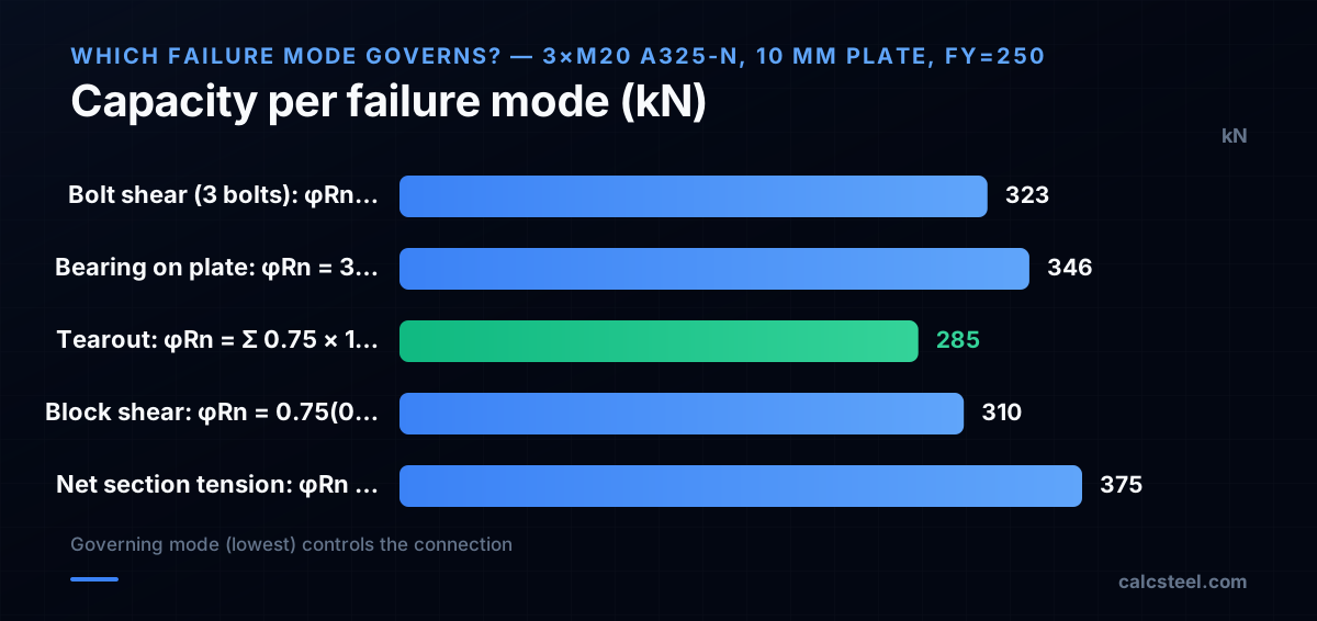
- For 3 bolts: φR_n_total = 3 × 107.7 = 323 kN
If the factored load P_u ≤ 323 kN, the bolts pass in shear.
For double shear (bolts passing through three plies), the capacity doubles because each bolt has two shear planes.
Thread condition matters
A325-N (threads included): F_nv = 457 MPa A325-X (threads excluded): F_nv = 579 MPa
The -X condition gives 27% more capacity, but you must install the bolt so the thread length does not extend into the shear plane. This is reliably achievable only with careful detailing and bolt length selection.
How do you check bearing and tearout strength at bolt holes?
Even if the bolts are strong enough, the plate around the holes can fail by bearing deformation or tearout between the hole and the edge.
Bearing strength (AISC J3.10)
φR_n = φ × 2.4 × d × t × F_u
Where d = bolt diameter, t = plate thickness, F_u = plate ultimate strength.
For M20 bolt, 10 mm plate (F_u = 400 MPa): φR_n = 0.75 × 2.4 × 20 × 10 × 400 × 10⁻³ = 144 kN per bolt
Tearout strength (AISC J3.10)
φR_n = φ × 1.2 × L_c × t × F_u
Where L_c = clear distance from bolt hole edge to the nearest edge or adjacent hole.
For the end bolt with edge distance = 30 mm and hole diameter = 22 mm: L_c = 30 − 22/2 = 30 − 11 = 19 mm φR_n = 0.75 × 1.2 × 19 × 10 × 400 × 10⁻³ = 68.4 kN
For interior bolts with spacing = 60 mm: L_c = 60 − 22 = 38 mm φR_n = 0.75 × 1.2 × 38 × 10 × 400 × 10⁻³ = 136.8 kN
The total connection capacity is the sum of the governing value (min of bearing and tearout) at each bolt.
Total = 68.4 + 136.8 + 136.8 = 342 kN
Notice the end bolt's tearout capacity (68.4 kN) is much less than the interior bolts (136.8 kN). Increasing the edge distance to 40 mm would raise the end bolt tearout to 87 kN — a 27% improvement for no extra material.
What is block shear failure in a bolted connection?
Block shear occurs when a block of material tears out of the connected plate along a combination of shear and tension planes. It is critical for coped beams, gusset plates, and short connections.
The AISC equation (J4.3) is:
φR_n = φ × (0.6 × F_u × A_nv + U_bs × F_u × A_nt) ≤ φ × (0.6 × F_y × A_gv + U_bs × F_u × A_nt)
Where: - A_nv = net area along the shear plane(s) - A_nt = net area along the tension plane - A_gv = gross area along the shear plane(s) - U_bs = 1.0 for uniform tension, 0.5 for non-uniform tension - φ = 0.75
Checking block shear for our example
3 bolts in a single vertical line, 10 mm plate, edge distance 30 mm, spacing 60 mm:
Shear plane (along the bolt line): - Gross length: 30 + 2 × 60 = 150 mm - A_gv = 150 × 10 = 1500 mm² - Net deduction: 2.5 holes × 22 × 10 = 550 mm² (2 full + 1 half) - A_nv = 1500 − 550 = 950 mm²
Tension plane (perpendicular, at the top bolt): - Gross length: 30 mm (edge to bolt center) - A_nt = (30 − 22/2) × 10 = 190 mm²
φR_n = 0.75 × (0.6 × 400 × 950 + 1.0 × 400 × 190) × 10⁻³ = 0.75 × (228000 + 76000) × 10⁻³ = 0.75 × 304 = 228 kN
This is less than bolt shear (323 kN) and less than tearout (342 kN), so block shear governs this connection. The fix: add more edge distance, or widen the bolt pattern to a two-line arrangement.
When should you use slip-critical bolted connections?
AISC 360-22 Section J3.8 requires slip-critical connections in specific situations:
- Oversized or slotted holes — Slip into bearing would cause misalignment
- Connections subject to fatigue — Repeated slip causes fretting and crack initiation at bolt holes
- Connections with combined shear and tension on bolts — Where slip could cause progressive failure
- Seismic connections — Per AISC 341, certain seismic connections must be slip-critical
Slip resistance calculation
φR_n = φ × μ × D_u × h_f × T_b × n_s
Where: - φ = 1.0 (for service load check) or 0.85 (for strength-level check) - μ = mean slip coefficient: 0.30 (Class A, unpainted clean mill scale) or 0.50 (Class B, blast-cleaned) - D_u = 1.13 (ratio of mean installed bolt pretension to specified minimum) - h_f = filler factor (1.0 for no fillers) - T_b = minimum bolt pretension (from AISC Table J3.1) - n_s = number of slip planes
For M20 A325 bolt, Class A surface, single slip plane: - T_b = 142 kN (Table J3.1) - φR_n = 1.0 × 0.30 × 1.13 × 1.0 × 142 × 1 = 48.1 kN per bolt
Compare with bearing-type shear: 107.7 kN. Slip-critical capacity is less than half! This is why slip-critical connections require more bolts. But they prevent the slip that causes fatigue damage.
Class B surfaces (blast-cleaned) give μ = 0.50, which brings the slip capacity to 80.2 kN — much closer to bearing capacity. The cost of surface preparation pays off in fewer bolts.
How do you lay out a bolt group for maximum efficiency?
Bolt layout follows specific AISC rules (J3.3-J3.5) and practical guidelines:
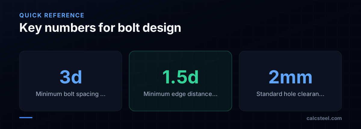
Minimum spacing - Center-to-center: 2⅔d (preferred 3d). For M20: minimum 53 mm, preferred 60 mm - Closer spacing makes bearing and tearout critical
Minimum edge distance - Standard holes: depends on bolt size and edge type (sheared vs rolled). For M20: 26 mm minimum (Table J3.4) - Preferred: 1.5d to 2d (30-40 mm for M20)
Maximum spacing and edge distance - Maximum spacing: min(24t, 305 mm) for painted members, min(14t, 178 mm) for unpainted - Maximum edge distance: 12t ≤ 150 mm - These limits prevent moisture entry and ensure load sharing
Practical layout rules
- Use standard gauges — W-shape flange gauges are tabulated in the AISC Manual (Table 1-7A). Using standard gauges means standard connection angles and fewer fabrication errors.
- Two vertical rows are better than one — Doubles block shear capacity and reduces eccentricity
- Stagger bolts when possible — Staggered patterns improve net section efficiency
- Keep bolt count manageable — More than 6-8 bolts in a line causes unequal load distribution. Group into two or more lines.
- Match plate thickness to bolt size — Rule of thumb: plate thickness ≥ bolt diameter for efficient bearing. Thinner plates waste bolt capacity.
How does CalcSteel design bolted connections automatically?
Manual bolt connection design requires checking five or more failure modes at every bolt location, for every load combination. CalcSteel automates this:
What the connection engine checks
- Bolt shear — Single or double shear, threads included or excluded, per bolt group
- Bearing and tearout — At every bolt, considering actual edge and spacing distances
- Block shear — All possible failure paths, including L-shaped and U-shaped patterns
- Net section rupture — Accounting for staggered holes via the s²/4g rule
- Combined shear and tension — The AISC elliptical interaction equation
- Slip resistance — When the connection is flagged as slip-critical
How the optimizer works
Given the demand forces at a node, the connection engine: - Selects bolt grade and diameter (starting from M16 A325-N) - Tries bolt patterns (single line, double line, staggered) with standard gauges - Checks all failure modes for the lightest combination - Reports the governing mode and the utilization ratio
The result is a fully code-compliant connection that you can verify against the hand calculation shown above. Every intermediate value — clear distance, net area, slip coefficient — is visible in the connection detail report.
When to intervene
The optimizer handles standard cases well, but some situations require engineering judgment: - Connections with eccentricity (bolt groups loaded off-center) - Moment connections with bolt groups in tension and compression - Connections at beam copes where multiple failure modes interact - Mixed connections with both bolts and welds
In these cases, override the auto-design and verify each limit state manually using the detailed output.
Try CalcSteel for free
Model, analyze and design steel structures in your browser. No install, no signup.
Open the 3D editor