Bending Moment in a Simply Supported Beam

Asking "how do I calculate bending moment on a simply supported beam?" sounds like a one-line formula question — and for the textbook cases it is: M = PL/4 for a central point load, M = wL²/8 for a uniform load, both at midspan. But behind those tidy results is a centuries-long argument about where a beam actually bends, and a modern software pipeline that turns the same physics into an automated capacity check against a design code.
Key takeaways
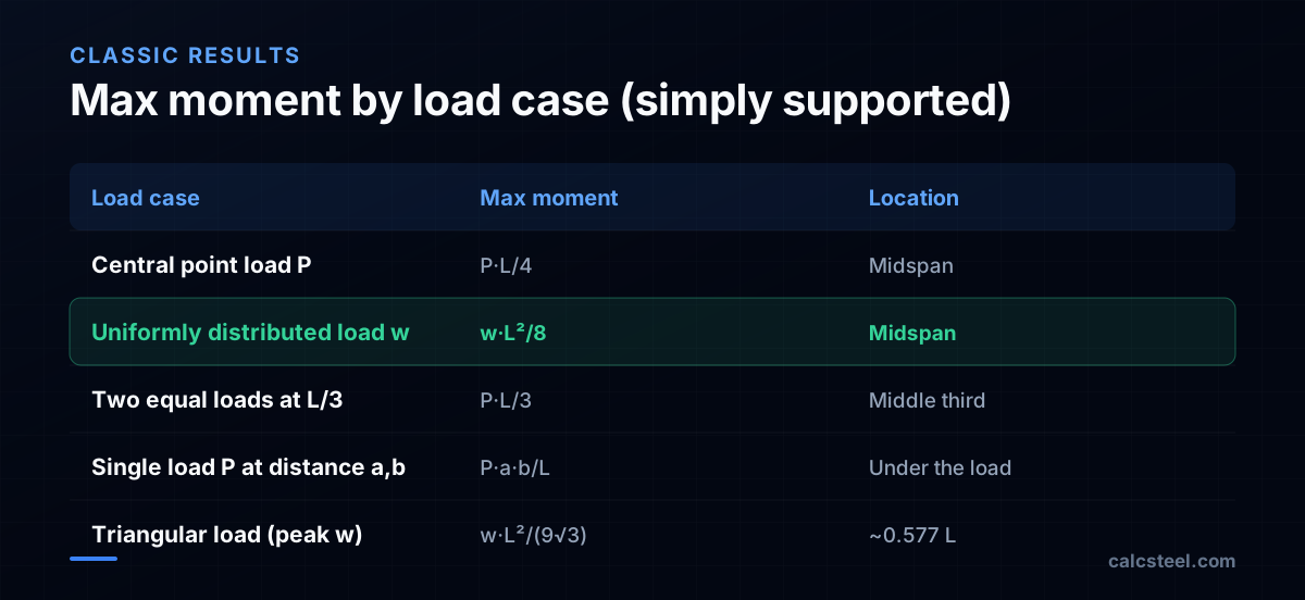
- For a simply supported span, max moment is PL/4 (central point load) or wL²/8 (uniform load), each at midspan — derived from statics alone.
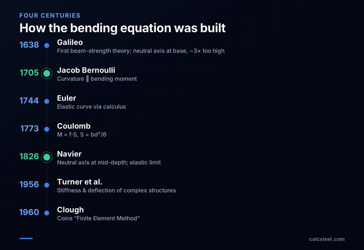
- Galileo published the first beam-strength theory in 1638 but put the neutral axis at the base, overestimating capacity ~3×; Coulomb (1773) and Navier (1826) gave the modern correct treatment.
- Finding the moment (demand) and proving the section is safe (capacity) are two separate steps — the second one depends entirely on your design code.
- Modern browser tools reduce the moment via finite elements, then auto-verify φMn ≥ Mu against AISC 360, Eurocode 3, NBR 8800 or IS 800.
The formula, and the question behind it
For a single span resting on two supports — a simply supported beam — the maximum bending moment from a central point load P is M = P·L/4, and from a uniformly distributed load w it is M = w·L²/8. In both cases the peak lands at midspan. These come straight from statics: split the load to the two reactions, then sum moments at the critical section.
The uniform-load case is worth doing by hand once. Each reaction carries wL/2. The moment at a distance x is M(x) = (wL/2)·x − w·x²/2. At midspan (x = L/2) that becomes wL²/4 − wL²/8 = wL²/8. Nothing about material, section shape or safety enters yet — and that is the real lesson. Calculating the moment answers “how hard is this beam being bent?” It does not answer “will it survive?” Those are two different problems, and history needed almost two centuries to fully untangle them.
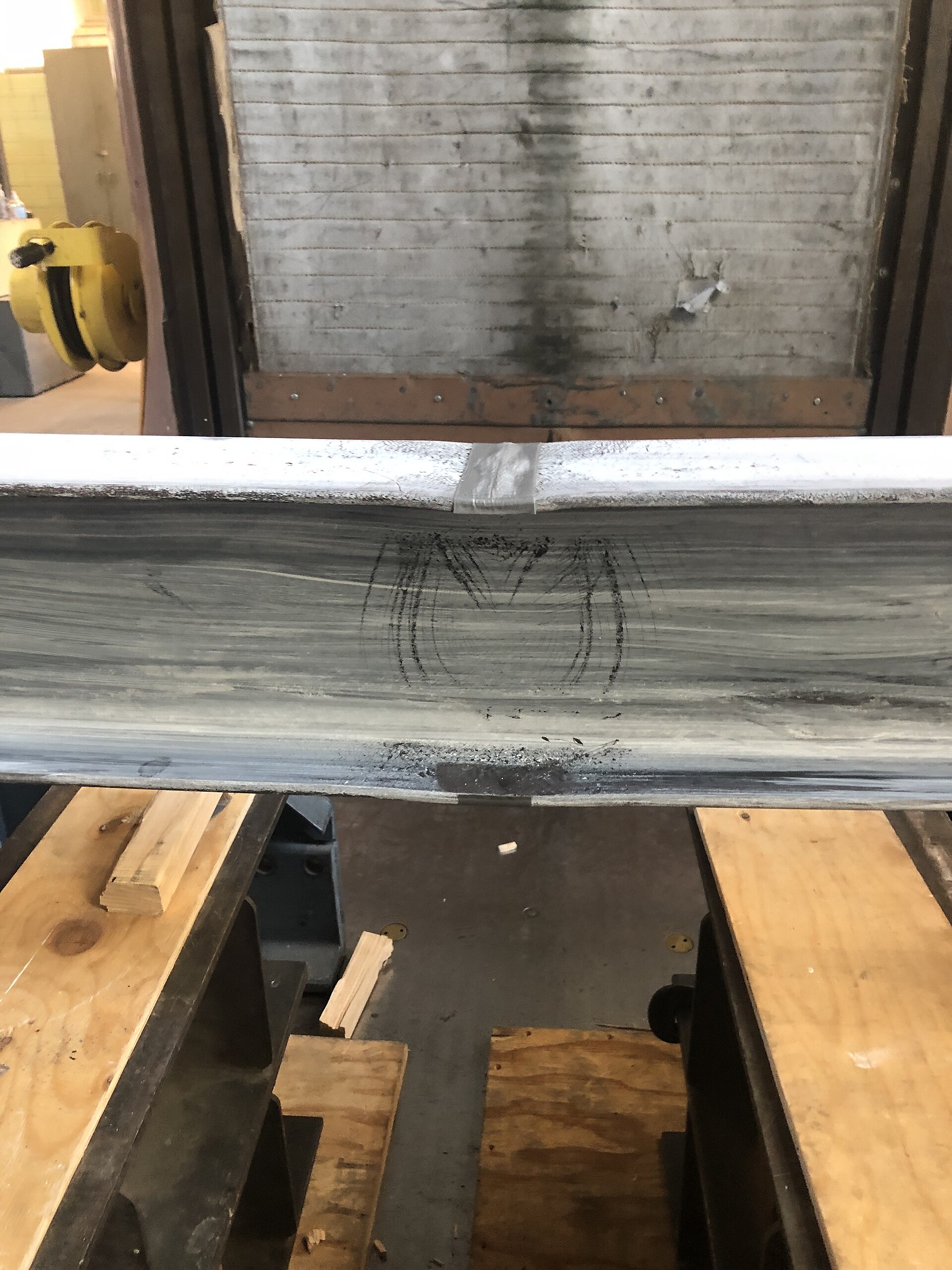
Galileo got the right question and the wrong axis
The first published theory of beam strength appears in Galileo's Two New Sciences (Discorsi) of 1638 — the book that opens the modern study of strength of materials. Galileo analysed a cantilever and assumed the section rotated about its base, with a uniform tensile stress across the whole depth equal to the material's tensile strength.
It was a brilliant framing of a problem nobody had formalised — and it was wrong. Putting the pivot at the bottom fibre and ignoring the linear stress distribution made his predicted bending strength roughly three times the correct value for a brittle, linear-elastic material. The honest historical verdict, widely repeated, is that Galileo identified the question of stress and strength but misplaced what we now call the neutral axis. Mariotte (1686) and Parent (1713) made the first corrections; fixing the assumption fully would take the rest of the Enlightenment.
Demand vs. capacity: the split engineers must keep straight
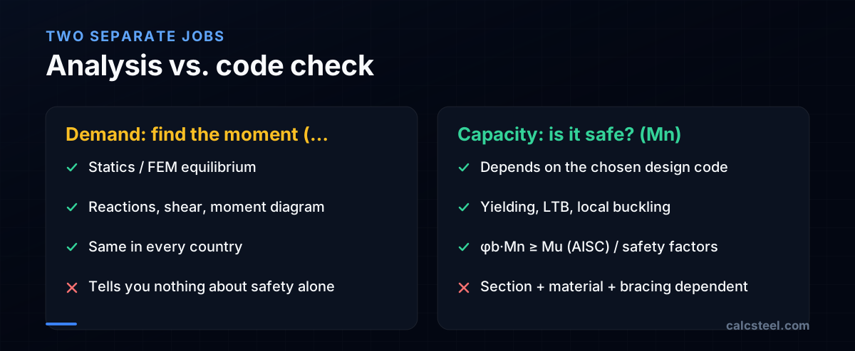
Here is the distinction that trips up beginners and that every serious tool enforces. Finding the moment (the demand, often written M or Mᵤ) is pure mechanics — equilibrium and geometry. It is the same in São Paulo, Stuttgart and Mumbai. Proving the beam can carry it (the capacity, Mₙ) is a code question: it depends on the section, the steel grade, and how the compression flange is braced against lateral-torsional buckling.
So wL²/8 is necessary but never sufficient. After computing the demand you must compare it to the design capacity — for example AISC's LRFD check φᵦ·Mₙ ≥ Mᵤ. Treat the two as one step and you can size a beam that is statically fine yet buckles sideways under a fraction of its plastic moment.
How software actually computes it
For the canonical cases, a tool could just look up PL/4 or wL²/8. Real structures aren't canonical: continuous spans, point loads at odd locations, settlements and frames. So modern engines use the finite element method — born from Turner, Clough, Martin and Topp's 1956 paper on the stiffness and deflection of complex structures, with Ray Clough coining the name “Finite Element Method” in 1960.
In practice the solver builds a global stiffness matrix from per-element beam stiffness terms, applies loads and boundary conditions, solves K·u = F for the nodal displacements, and recovers internal shear and moment along each element. The classic hand formula falls out as the special case of one simply supported element — a useful sanity check. CalcSteel runs exactly this kind of pipeline: a Python finite-element backend does the matrix solve, and a React/TypeScript front end draws the moment diagram in the browser, no install required.
Verdict: know the formula, let the tool prove the section
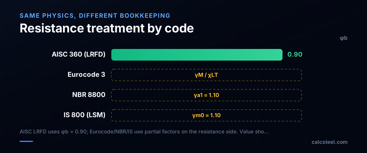
If you only remember two things: max moment on a simply supported span is PL/4 or wL²/8 at midspan, and that number is only half the answer. The other half — capacity — is where design codes diverge. AISC 360 (LRFD) applies a resistance factor φᵦ = 0.90 to the nominal moment; Eurocode 3 reduces capacity with the lateral-torsional buckling factor χʟᴛ and partial factors; NBR 8800 (γₐ₁ = 1.10) and IS 800 (γₘ₀ = 1.10) use their own partial factors. Same physics, different bookkeeping.
That is precisely the gap good software closes. The CalcSteel editor is browser-native (free plan available, with Pro reported at US$24/month billed annually), carries 1,140+ steel profiles, runs the moment via its Python FEM solver, and then auto-checks the section against NBR 8800, AISC 360, Eurocode 3 or IS 800 — turning the hand formula into a full, code-compliant verification in seconds.
Sources
- 1.Turner, Clough, Martin & Topp (1956), Stiffness and Deflection Analysis of Complex Structures — Journal of the Aeronautical Sciences
- 2.Ray W. Clough (1960), The Finite Element Method in Plane Stress Analysis
- 3.Euler–Bernoulli beam theory — Wikipedia (Bernoulli 1705, Euler 1744)
- 4.Historical development of the beam bending equation M = fS (Galileo, Coulomb 1773, Navier 1826)
- 5.The history of the theory of beam bending — Newton Excel Bach (Galileo's ~3× overestimate)
- 6.Steel Profile Catalog — 1140+ AISC, Eurocode, NBR & IS Sections | CalcSteel
- 7.Image: Scu ba — CC0 (Wikimedia Commons)
Try CalcSteel for free
Model, analyze and design steel structures in your browser. No install, no signup.
Open the 3D editor