Beam for a 10 m Clear Span: Three Candidate Sections, and the One That Wins

"What beam for a 10 m clear span?" sounds like a lookup, and for strength it almost is. This deep-dive puts one real floor beam through the CalcSteel FEM engine, hand-checks the moment against wL squared over 8, and races three candidate sections, IPE 360, IPE 400 and IPE 450, through strength, shear and both deflection limits. The twist: all three pass strength comfortably, the moment never decides, and the section that wins is the one a strength table would never make you buy, because on a 10 m span deflection is the governing check.
Key takeaways
- A beam for a 10 m clear span is almost never sized by its bending moment. On this worked floor beam the ULS demand is a peak moment of 285 kN·m, and all three candidates, IPE 360, IPE 400 and IPE 450, carry it with room to spare (utilisation 0.88, 0.68 and 0.52), so strength alone does not pick the section.
- Deflection is the governing check on a long span, because the demand grows with L to the fourth while the bending moment only grows with L squared. Under the service loads the L/360 live limit is 27.8 mm and the L/250 total limit is 40.0 mm, and those two numbers, not the moment, decide the winner.
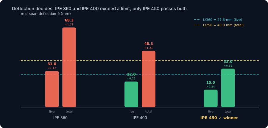
- The IPE 360 has ample strength (0.88) but deflects 31.0 mm under live load and 68.3 mm under the total load, failing both limits. The IPE 400 clears the live limit at 22.0 mm but still deflects 48.3 mm under the total load, failing L/250. Only the IPE 450, at 15.0 mm and 33.0 mm, passes every check, so it wins.
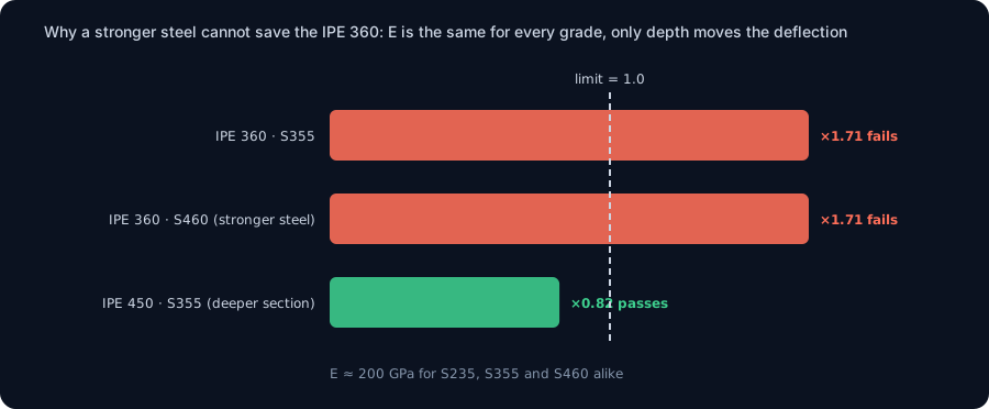
- A stronger steel cannot save the failing section. The elastic modulus E is about 200 GPa for S235, S355 and S460 alike, and deflection depends only on E and the second moment of area, not on yield strength. Upgrading the IPE 360 to S460 lifts its strength margin and leaves its deflection exactly where it was, still failing. The only levers are more depth, a shorter span, precamber or composite action.
- The engine matches closed-form theory: wL squared over 8 for the moment and wL over 2 for the shear and reaction to four decimals, and 5wL to the fourth over 384EI for the deflection to within the fillet idealisation. The governing case is computed from equilibrium, not remembered from a table.
The question that looks like a lookup, and why it is not
Ask a structural engineer "what beam for a 10 m clear span" and the fast answer is a section off a table. Pick the shape whose bending capacity beats the moment, done. For a short beam that answer is even correct, because on a short span strength is what runs out first. The trap is that a 10 m clear span is not short, and on a long span the check that runs out first is not strength at all. It is deflection.
This article works one concrete beam all the way through and lets the numbers settle the question. A simply supported floor beam, 10.0 m between supports, carrying a light commercial floor. We solve it on the CalcSteel finite element engine, cross-check the moment and shear against hand statics, then race three candidate sections, an IPE 360, an IPE 400 and an IPE 450, through strength, shear and the two deflection limits. Here is the whole point in advance: every one of the three has more than enough bending strength, the moment never picks a winner, and the section that wins is the deepest and heaviest of the three, chosen not by its capacity but by how little it sags.
The worked beam: 10 m, simply supported, a floor over it
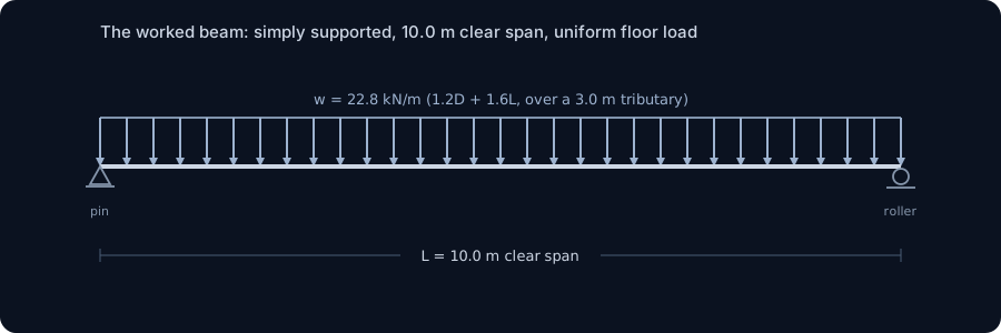
Here is the member we carry through the article. A simply supported single span of L = 10.0 m, pinned at one end and on a roller at the other, one line in a floor grid where the beams sit 3.0 m apart, so this beam collects a 3.0 m wide strip of floor. The compression flange is held all along its length by the slab or the steel deck bearing on it, so lateral-torsional buckling is not the story here, this is a beam braced against sideways buckling and free to develop its full in-plane bending. That leaves exactly two things that can size it: the strength to carry the moment, and the stiffness to keep the floor from sagging too far.
Two facts about a 10 m span decide everything downstream. First, the span is long, and deflection scales with the fourth power of the span while the bending moment scales only with the square, so as spans stretch the two checks pull apart and stiffness overtakes strength. Second, this is a floor, and a floor has an occupant who feels a bouncy or visibly sagging beam long before it is anywhere near its strength. Hold on to both, because together they are why the winner is not the lightest section that carries the load.
One load, three checks, and two deflection limits
Take the floor pressures over the 3.0 m spacing and each becomes a line load along the beam. A light commercial floor gives a permanent (dead) load of about 3.0 kN/m2 for the slab, deck, screed and services, and an imposed (live) load of about 2.5 kN/m2. Over the 3.0 m strip:
- Dead load D = 3.0 x 3.0 = 9.0 kN/m.
- Live load L = 2.5 x 3.0 = 7.5 kN/m.
Strength is checked at the factored (LRFD) load. The gravity combination is 1.2D + 1.6L = 1.2 x 9.0 + 1.6 x 7.5 = 22.8 kN/m, and that single line load drives the moment and shear. Serviceability is checked at the unfactored service loads, and there are two of them, because two things must stay small: the deflection under live load only, which the occupant feels day to day, and the deflection under the full load, which the finishes and the eye see. So three demands come out of one beam:
- Strength, from w = 22.8 kN/m.
- Live deflection, from the live line load of 7.5 kN/m, limited to L/360 = 10000/360 = 27.8 mm.
- Total deflection, from the full service line load D + L = 16.5 kN/m, limited to L/250 = 10000/250 = 40.0 mm.
Notice we have not chosen a section yet. The demand side is the same for every candidate, it comes from the span and the load, not from the steel. That is what makes the comparison clean: three sections, one set of demands, and we watch which checks each section passes.
The demand, and a hand check that matches to the digit
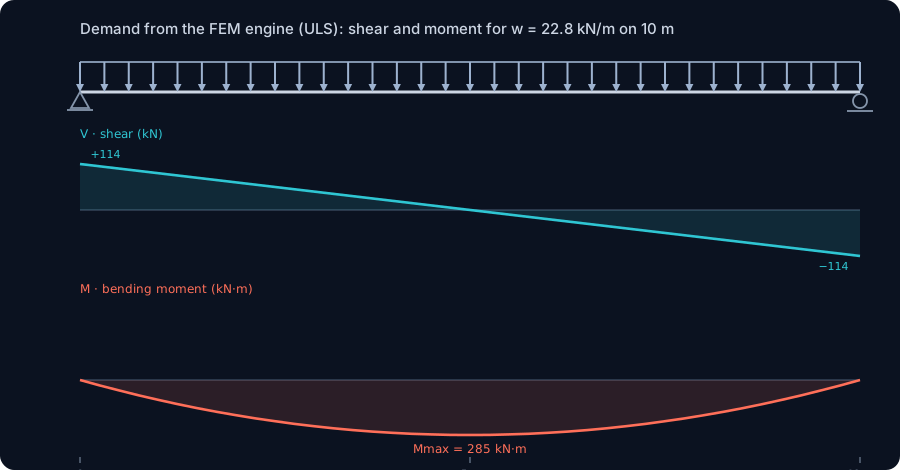
Drop the beam into the CalcSteel engine, apply the factored line load of 22.8 kN/m, and read the diagrams. For a simply supported span under a uniform load the answer is the most familiar in structural engineering, and the engine returns it exactly:
- Peak bending moment at midspan, M = 285.0 kN·m, matching wL squared over 8 = 22.8 x 10 squared / 8 = 285.0 to four decimals.
- Peak shear at the supports, V = 114.0 kN, matching wL over 2 = 22.8 x 10 / 2 = 114.0.
- Each reaction 114.0 kN down into the support.
That 285 kN·m is the number every candidate has to beat in strength, and 114 kN the shear. Both are fixed by the span and the load. What changes from section to section is the capacity that meets them, and, crucially, the deflection, which the diagram above does not show but the engine also reports. Keep the moment of 285 kN·m in mind, because in a moment we will see all three candidates clear it, and then watch a much quieter number decide the beam.
Try it: put your own 10 m span in
Before the three-way race, get a feel for the demand yourself. The calculator below is the CalcSteel beam calculator. Enter a span of 10 m, a uniform load of 22.8 kN/m and simple supports, and it returns the reactions, the shear and bending-moment diagrams and the mid-span deflection, the same 285 kN·m and 114 kN the engine gave above. Then swap in a service load of 16.5 kN/m and read the deflection it reports for your chosen section: that single number, not the moment, is the one that decides a 10 m beam.
Max moment
45 kN·m
Max shear
30 kN
Max deflection
10.55 mm
= L/569
Bending stress σ
84.4 MPa
σ = M/Sx
Utilization
44.0%
NBR 8800 · δ ≤ L/250
Geometry & supports
Section
Ix 7999 cm⁴ · Sx 533 cm³ · 42.2 kg/m
Point loads (↓ positive)
None — add as many as you need.
Distributed loads (uniform or trapezoidal)
Model sketch
Diagrams — free PNG / SVG / CSV export, no watermark
Step-by-step — the calculation memory of YOUR beam
IPE 300 · L = 6 m · fy = 250 MPa
1. Reactions (equilibrium of the solved FEM model)
ΣFy = 0 · ΣM = 0
R_A = 30 kN · R_B = 30 kN
2. Peak shear (read from the SFD)
Vmax = |V(x)|max
Vmax = -30 kN @ x = 6 m
3. Peak moment (read from the BMD)
Mmax = |M(x)|max
Mmax = 45 kN·m @ x = 3 m
4. Peak deflection
EI = 15998 kN·m² (E = 200 GPa)
δmax = 10.55 mm @ x = 3 m = L/569
5. Elastic bending stress
σ = Mmax / Sx = 45.00 × 10³ / 533.3
σ = 84.4 MPa
6. Bending check — both codes, side by side
NBR 8800: σ ≤ fy/1.10 = 227.3 MPa · AISC 360: σ ≤ 0.90·fy = 225 MPa
NBR 37.1% PASS · AISC 37.5% PASS
7. Deflection check (serviceability — code-independent)
δ ≤ L/250 = 24 mm
10.55 mm / 24 mm = 44.0% PASS
Recomputed live from the current inputs by the direct-stiffness FEM engine — change any load and every step updates. Reproduce it by hand with the formulas in the sections below.
Lightest catalog profiles that pass (974 flexural candidates · NBR 8800)
| Profile | Std | Weight | Total steel | σ util | δ util | |
|---|---|---|---|---|---|---|
| W310x21 | AISC | 21 kg/m | 126 kg | 83% | 98% | |
| VS 300x23 | BR | 22.6 kg/m | 136 kg | 71% | 84% | |
| U 300x90x6.3 | BR | 23.1 kg/m | 139 kg | 82% | 98% | |
| U 300x100x6.3 | BR | 24.1 kg/m | 145 kg | 77% | 91% | |
| VS 250x25 | BR | 24.6 kg/m | 148 kg | 70% | 100% |
Elastic bending (σ = M/Sx vs fy/γa1, γa1 = 1.10 — NBR 8800) + deflection screening of the full flexural catalog. Lateral-torsional buckling, shear and local buckling are NOT checked here — run the full NBR 8800 / AISC 360 verification in the 3D editor.
The three candidates
Line up three sections that a span table might hand you for a 10 m bay, all in grade S355 (yield strength fy = 355 MPa). They step up in depth, and with depth comes both strength and stiffness, but at a weight cost:
| Section | Depth | Second moment Ix | Elastic modulus Sx | Plastic modulus Zx | Mass |
|---|---|---|---|---|---|
| IPE 360 | 360 mm | 16 270 cm4 | 904 cm3 | 1019 cm3 | 57.1 kg/m |
| IPE 400 | 400 mm | 23 130 cm4 | 1156 cm3 | 1307 cm3 | 66.3 kg/m |
| IPE 450 | 450 mm | 33 740 cm4 | 1500 cm3 | 1702 cm3 | 77.6 kg/m |
Read the two right-hand columns before we start. The modulus that sets bending strength, Zx, climbs modestly from 1019 to 1702 cm3, about 67 percent, across the three. The second moment of area Ix, which sets deflection, climbs from 16 270 to 33 740 cm4, more than double. Depth helps stiffness far more than it helps strength, because deflection depends on Ix, which grows with roughly the cube of the depth, while strength depends on the modulus, which grows only with the square. That gap is the whole reason a strength winner and a deflection winner can be different sections, and on a 10 m span they are.
Strength: all three pass, so strength does not decide
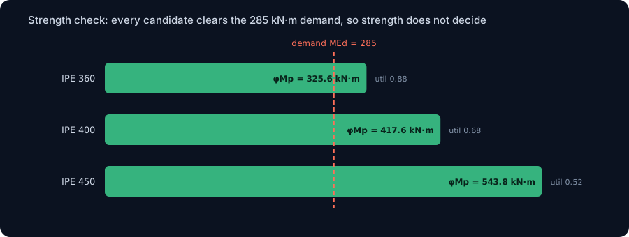
Check each section for the 285 kN·m moment. All three IPE shapes are compact (Class 1) in S355 and their compression flange is braced by the slab, so each reaches its full plastic moment, Mp = fy x Zx, and the design capacity is phi·Mp with the resistance factor phi = 0.90:
| Section | Plastic moment Mp | Design capacity phi·Mp | Moment demand | Strength utilisation |
|---|---|---|---|---|
| IPE 360 | 361.7 kN·m | 325.6 kN·m | 285 kN·m | 0.88 |
| IPE 400 | 464.0 kN·m | 417.6 kN·m | 285 kN·m | 0.68 |
| IPE 450 | 604.2 kN·m | 543.8 kN·m | 285 kN·m | 0.52 |
Every candidate clears the demand. Even the lightest, the IPE 360, sits at 0.88, inside its capacity with margin to spare. Shear is nowhere near governing either: the factored shear of 114 kN runs against a web shear capacity of roughly 550 kN on the IPE 360, a utilisation near 0.2, and it only falls from there on the deeper sections. If strength were the whole story we would take the IPE 360, the cheapest section that passes, and stop. A span table would do exactly that. Hold that thought, because it is about to be wrong.
Deflection decides, and it eliminates two of the three
Now the check the table cannot show you. Solve each candidate for the two service loads and read the mid-span deflection the engine reports, then compare it against its limit. Deflection follows 5wL to the fourth over 384EI, and because it grows with the fourth power of the span, a 10 m beam sags far more, for the same load, than the short beams the strength check is comfortable with.
| Section | Live deflection (L/360 = 27.8 mm) | Total deflection (L/250 = 40.0 mm) | Verdict |
|---|---|---|---|
| IPE 360 | 31.0 mm, utilisation 1.12 | 68.3 mm, utilisation 1.71 | fails both |
| IPE 400 | 22.0 mm, utilisation 0.79 | 48.3 mm, utilisation 1.21 | fails total |
| IPE 450 | 15.0 mm, utilisation 0.54 | 33.0 mm, utilisation 0.82 | passes both |
Read it top to bottom. The IPE 360, the strength winner at 0.88, sags 31.0 mm under live load alone against a 27.8 mm limit, and 68.3 mm under the full load against a 40 mm limit. It fails both, badly, on a section that had strength to spare. The IPE 400 is stiffer: it clears the live limit at 22.0 mm, but under the full service load it still sags 48.3 mm, over the 40 mm limit, so it fails too. Only the IPE 450, at 15.0 mm live and 33.0 mm total, sits under both limits. The moment demand was identical for all three, 285 kN·m, and the moment never mattered. The beam is chosen by the quietest column in the table.
A quick hand check keeps the engine honest. For the IPE 400 under the full service load, 5wL to the fourth over 384EI with w = 16.5 kN/m, L = 10 m, E = 200 GPa and the tabulated Ix = 23 130 cm4 gives 46.4 mm. The engine reports 48.3 mm, a few percent higher, because its section model idealises the rolled fillets and so carries a second moment of area about 3 percent below the table. Both land above the 40 mm limit, so the verdict is the same either way: the IPE 400 fails the total-deflection check.
The winner: IPE 450, and the scorecard that names it
Put every check on one card and the answer is unambiguous. The winning section is the lightest one that passes every check, and on a 10 m span that is the IPE 450:
| Check | IPE 360 | IPE 400 | IPE 450 |
|---|---|---|---|
| Strength (phi·Mp vs 285) | 0.88 | 0.68 | 0.52 |
| Live deflection (L/360) | 1.12, fails | 0.79 | 0.54 |
| Total deflection (L/250) | 1.71, fails | 1.21, fails | 0.82 |
| Span-to-depth L/d | 27.8 | 25.0 | 22.2 |
| Mass | 57.1 kg/m | 66.3 kg/m | 77.6 kg/m |
| Verdict | rejected | rejected | selected |
The IPE 450 is 36 percent heavier than the IPE 360 that had all the strength, and it is worth every kilogram, because the extra steel buys stiffness the strength check never asked for and the floor genuinely needs. Look at the last-but-two row: the winner sits at a span-to-depth ratio of about 22, right inside the 20 to 24 band that experienced designers reach for on a floor beam precisely because it tends to keep deflection in check, while the failing IPE 360 sits at 28, too shallow for its span. The rule of thumb and the calculation agree, and the calculation is what you submit.
Why a stronger steel would not save the loser
The instinct after a failed check is to reach for a stronger steel. Here that lever does nothing, and the reason is worth internalising because it catches people. Deflection is 5wL to the fourth over 384EI, and the only material property in it is E, the elastic modulus. For structural steel E is about 200 GPa for every grade, S235, S355, S460, all the same. Yield strength does not appear. So upgrading the IPE 360 from S355 to S460 raises its plastic moment and pushes its strength utilisation down from 0.88 to about 0.68, more margin on a check that already passed, and leaves its deflection at exactly 31.0 mm and 68.3 mm. It fails the two deflection limits by the identical amount it did before. You bought stronger steel and fixed nothing.
Deflection has only a handful of real levers, and grade is not one of them. More depth (a larger Ix, which is why the IPE 450 wins), a shorter span (add an intermediate support and the L to the fourth term collapses), precamber (curve the beam up in the shop to cancel the dead-load sag), or composite action (connect the beam to the slab so they bend together and the effective Ix jumps). On this beam, if headroom rules out going to the IPE 450, precamber is the elegant fix: the dead load causes about 26 mm of the IPE 400's total sag, so cambering it out leaves only the 22 mm live-load part, which sits under both limits. Same section, a shop bend, and the loser passes. But reach for a stronger steel and the deflection does not move a millimetre.
What the codes ask, on three continents
The workflow, factored load for strength then service load for deflection against a span-fraction limit, is the same everywhere. The packaging differs.
- United States (AISC 360 with ASCE 7). Strength by LRFD, phi·Mn against the factored 1.2D + 1.6L. Deflection is a serviceability matter left to the IBC and to project criteria, commonly L/360 for live load and L/240 for total load on floor members supporting brittle finishes. The principle, that a long-span floor is usually deflection-governed, is standard guidance.
- Europe (EN 1993-1-1 with EN 1990). Strength at the ultimate limit state, MEd against Mc,Rd. Deflection at the serviceability limit state, with the characteristic combination and limits set in the National Annex, often around L/350 for the variable-action deflection and L/250 for the total, and precamber is explicitly allowed to be deducted.
- Brazil (NBR 8800). The same two limit states, strength at the ELU and deflection at the ELS, with the serviceability displacement limits tabulated (floor beams commonly L/350 for the live part and L/250 total). The IPE catalogue this example uses maps directly onto the W and VS shapes the Brazilian market rolls.
Different symbols, one idea. Every one of these codes checks strength against a factored load and deflection against a service load, and on a 10 m span it is the second check that bites. CalcSteel runs both from the same model, forms the combinations and reports the governing utilisation for AISC 360, Eurocode 3 and NBR 8800 at once, so the deflection case is computed rather than remembered. For the load side, our note on load combinations covers where 22.8 and 16.5 kN/m came from, and our guide to serviceability, deflection and vibration goes deeper on the limits.
Common mistakes and FAQ
"Pick the section whose capacity beats the moment, then stop." That is the strength check, and on a 10 m span it is the check that does not govern. Here it would hand you the IPE 360 at utilisation 0.88, a section that then sags 68 mm and fails the floor. Beating the moment is necessary, not sufficient.
"The biggest moment picks the beam." The moment was identical, 285 kN·m, for all three candidates, and it separated none of them. What separated them was Ix, the second moment of area, which does not appear in the moment at all. On a long span the deciding property is stiffness, not strength.
"Use a higher-strength steel to fix the deflection failure." Deflection depends on E, which is about 200 GPa for every steel grade, not on yield strength. A stronger steel raises capacity and leaves deflection untouched. To reduce deflection you need more depth, a shorter span, precamber or composite action.
"Deflection is just an aesthetic nicety." On a floor it is a real limit: too much live-load deflection feels bouncy and cracks partitions and ceilings, too much total deflection ponds water on a roof or shows as a visible sag. That is why codes cap both, and why the cap, not the moment, sizes long-span floor beams.
"A 10 m span in steel is unusual." It is routine, and it is exactly the span where the strength-versus-stiffness gap opens up. For much longer spans the answer often changes shape entirely, to a composite beam, a castellated or cellular section, or a truss, precisely to buy stiffness and depth without unlimited weight.
From a span number to the governing check
So, what beam for a 10 m clear span? Not the lightest one whose capacity beats the moment. On this floor the IPE 360 has all the strength you need and fails the beam, the IPE 400 is stiffer and still fails the total-deflection limit, and the IPE 450 is the section that wins, chosen not for its capacity but because it keeps the sag under 40 mm. The section is an output of the governing check, and on a 10 m span that check is deflection.
The demand side is not guesswork, it is equilibrium: the engine reproduced wL squared over 8 and wL over 2 to four decimals, and 5wL to the fourth over 384EI to within the fillet idealisation. The judgement lives in knowing which limit bites, and on a long span it is stiffness, governed by E and Ix, not strength. CalcSteel runs the load cases, forms the combinations and reports the governing strength and deflection check for every candidate at once, so the deflection case is computed, not forgotten. Model your own 10 m beam in the editor, race a few sections, and watch the deflection column, not the moment, name the winner. For the mechanism behind the numbers, our guides to deflection limits and moment of inertia cover the stiffness that decides a long span.
Sources
- 1.AISC 360, Specification for Structural Steel Buildings (flexural strength, LRFD)
- 2.ASCE 7, Minimum Design Loads and Associated Criteria for Buildings and Other Structures (load combinations, serviceability)
- 3.EN 1993-1-1, Eurocode 3: Design of steel structures, Part 1-1, and EN 1990 (serviceability limit states, deflection limits)
- 4.ABNT NBR 8800, Projeto de estruturas de aco e de estruturas mistas de aco e concreto de edificios (ELU and ELS, deflection limits)
- 5.Steel Construction Institute, Steel Designers Manual (span-to-depth ratios and deflection control for floor beams)
Try CalcSteel for free
Model, analyze and design steel structures in your browser. No install, no signup.
Open the 3D editor