Yield Strain: the Criterion Behind the Code, With a Worked Check
Steel design is written in stress, but a steel fibre fails a strain test first. Yield strain, εy = fy/E, is about 0.12% to 0.18% for structural steel and it is the real trigger behind every code check. Here is what it means, why the code hides it inside fy, and a worked check on a real IPE 300 beam, verified by the CalcSteel engine.
Key takeaways
- Yield strain is εy = fy/E: about 0.00125 (0.125%) for 250 MPa steel and 0.001725 for a 345 MPa grade, both on the same stiffness E = 200 GPa.
- The code writes its limits in stress (fy) only because stress is easy to tabulate; the physical trigger is always the extreme fibre reaching εy.
- For steels without a sharp yield point, fy is defined at 0.2% plastic offset, so the code's strength is literally a strain measurement: ε = 0.002 + fy/E.
- Worked IPE 300 beam (L = 6 m, w = 20 kN/m): the CalcSteel engine gives Mmax = 90.0 kN·m, so the outer fibre sits at ε = 0.000834, which is 67% of MR250's yield strain and 48% of A572-50's.
- Push the same beam to w = 29.99 kN/m and the engine returns σ = 250.0 MPa, ε = 0.001250 = εy: first yield, confirmed to the fourth decimal.
The strain every steel clause is quietly built on
Every steel design check you run, whether it is bending, axial load, shear or the interaction equation, ends in a comparison against fy, the yield strength. That is a stress. But steel does not carry a stress sensor; it carries deformation. What actually decides whether a fibre has yielded is whether it has stretched past a certain strain, the yield strain εy. Stress is the bookkeeping; strain is the physics.
For structural steel that strain is small and remarkably consistent: about 0.00125 (0.125%) for a 250 MPa steel, and it barely passes 0.0018 even for the strongest common grades. Everything the code layers on top of it, the safety factors, the slenderness limits, the plastic-design rules, assumes that number. This article unpacks εy = fy/E from first principles, shows where the 0.2% offset comes from, and then runs a real IPE 300 beam through the CalcSteel FEM engine to check, to the fourth decimal, exactly when its outer fibre reaches yield strain.
What yield strain actually is
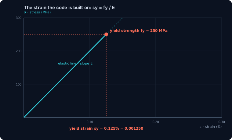
Here is a definition you can quote: yield strain is the tensile or compressive strain at which a steel fibre stops behaving elastically and starts to yield. For a linear-elastic material it is εy = fy/E, the yield stress divided by the modulus of elasticity.
It is a pure number, dimensionless, because it is a length change divided by a length (millimetres per millimetre). Engineers write it three equivalent ways: as a decimal (0.00125), as a percentage (0.125%), or in microstrain (1250 µε), the unit a strain gauge reports. All three describe the same event: a one-metre bar of 250 MPa steel has stretched 1.25 mm at the instant its fibre yields.
Two things make εy special. First, it is a material property, not a member property: it does not care whether the steel is a beam, a column or a bolt. Second, because E is nearly identical for every structural steel, εy is set almost entirely by the grade, which is exactly why the code can tabulate fy and never once mention strain.
Why the code speaks in stress and nature speaks in strain
If strain is the real trigger, why does no design clause mention it? Because of a convenient accident of steel: its stiffness barely changes. Mild steel, high-strength low-alloy steel and quenched-and-tempered steel all share a modulus of elasticity within a couple of percent of E = 200 GPa. (AISC and NBR 8800 adopt 200 GPa; Eurocode uses 210 GPa.) One slope, for every grade.
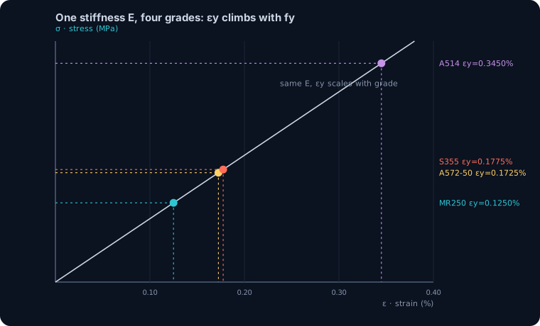
That single fact collapses strain and stress into interchangeable quantities. On a stress-strain plot, all structural steels ride up the same elastic line from the origin; the only thing the grade changes is how far up that line the steel yields. A 250 MPa steel steps off at εy = 0.125%; a 345 MPa steel rides the same line to 0.173%; a 690 MPa steel to 0.345%. The code prints the vertical coordinate (fy, a stress) because it is easy to measure and easy to tabulate, but the horizontal coordinate (εy, a strain) is doing the actual work. Change E and the whole mapping shifts; hold E fixed and fy is just εy in disguise.
εy = fy/E, grade by grade
The relationship is Hooke's law rearranged. In the elastic range σ = E·ε, so at the yield point σ = fy gives εy = fy/E. Nothing more. The table runs that division for the grades you meet most, using E = 200 GPa.
| Grade | fy (MPa) | εy = fy/E | as % | µε |
|---|---|---|---|---|
| ASTM A36 / MR250 | 250 | 0.001250 | 0.125% | 1250 |
| ASTM A572 Gr.50 / A992 | 345 | 0.001725 | 0.173% | 1725 |
| EN S355 | 355 | 0.001775 | 0.178% | 1775 |
| ASTM A514 / EN S690 | 690 | 0.003450 | 0.345% | 3450 |
Notice the spread: the strongest structural steel yields at under three times the strain of the mildest. Yield strain lives in a narrow band, roughly 0.12% to 0.35%, and for ordinary building steel it is essentially 0.12% to 0.18%.
One nuance worth carrying: Eurocode 3 adopts E = 210 GPa rather than 200, which nudges every εy down by about 5% (S355 becomes 0.00169 instead of 0.00178). It changes the strain, not the design stress, a reminder that εy is a derived quantity that inherits whatever E your code declares.
The 0.2% offset: when yield strain is the definition
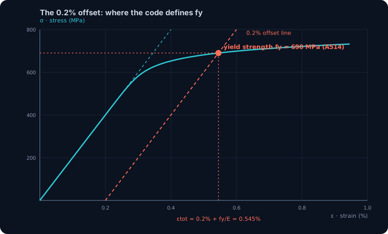
Everything so far assumed a clean yield point, the sharp knee that mild steel shows. But quenched-and-tempered steels, cold-formed sections and most high-strength grades have no knee; their curve rounds over smoothly with no obvious instant of yield. For those, the code has to invent a yield point, and it does so with a strain.
The rule is the 0.2% offset: draw a line parallel to the elastic slope but shifted 0.2% (0.002) along the strain axis; where it cuts the stress-strain curve, that stress is fy. Read that again: the code's strength is defined by a strain construction. The total strain at that point is ε = 0.002 + fy/E, the 0.2% permanent (plastic) set plus the elastic part that springs back. For a 690 MPa steel that is 0.002 + 0.00345 = 0.00545, or 0.545% total strain.
This is the deepest sense in which yield strain is the criterion behind the code: for a large class of steels, fy is not a stress the material announces, it is a stress we back-calculate from a strain we chose.
After yield strain: the plateau plastic design spends
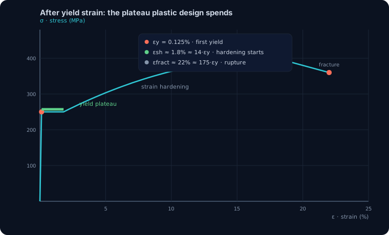
Reaching εy is not failure; it is the start of steel's best trick. A mild-steel fibre that hits εy does not keep climbing the elastic line, it flattens onto a yield plateau, flowing at roughly constant stress fy while the strain runs on. That plateau typically extends to a strain of order 1.5% to 2% before strain hardening begins, roughly 10 to 15 times εy. Only after the plateau does the curve rise again toward the ultimate stress fu, then fall to fracture near 20% to 25% elongation.
That long, flat reserve is what the whole edifice of ductile design spends. Plastic analysis, moment redistribution, seismic energy dissipation, the very idea of a plastic hinge, all of them assume a fibre can sit at εy and keep straining without shedding load. It is why the codes demand a minimum fu/fy ratio (about 1.1 to 1.25) and a minimum elongation: they are buying plateau length. A steel that yielded and immediately fractured would meet the same fy and be lethal to design with. Yield strain marks the door; the plateau is the room you get to use behind it.
Worked check, part 1: a real IPE 300 beam
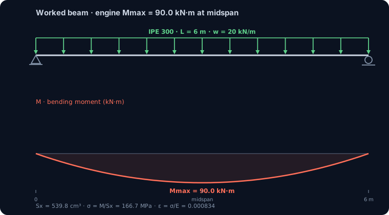
Time to make it concrete. Take a simply supported IPE 300 beam spanning L = 6 m under a uniform load w = 20 kN/m, a routine floor beam. We model it in the CalcSteel FEM engine, the same solver behind the calculators, and read the results rather than trust a formula.
The engine returns a maximum bending moment Mmax = 90.0 kN·m at midspan, matching the hand value wL²/8 = 20·6²/8 = 90.0 kN·m to the decimal. For the cross-section it computes an elastic section modulus Sx = 539.8 cm³ and second moment Ix = 8097 cm⁴. (Sx sits about 3% under the handbook 557 cm³ because the engine builds properties from the rolled dimensions with simplified fillets, a conservative and self-consistent value.) Those three numbers, the moment from the analysis and the section modulus from the geometry, are all we need to turn a load into a strain.
Worked check, part 2: is the outer fibre at yield strain?
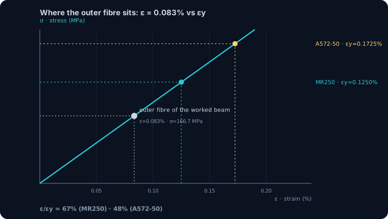
The extreme-fibre stress is σ = M/Sx. In consistent units, σ = 9000 kN·cm / 539.8 cm³ = 16.67 kN/cm² = 166.7 MPa. Divide by the modulus to get the strain the fibre is actually feeling: ε = σ/E = 166.7 / 200000 = 0.000834, that is 0.0834%.
Now the comparison the code makes for you, done explicitly. Against MR250 (εy = 0.00125) the fibre sits at 0.000834 / 0.00125 = 67% of yield strain. Against A572 Gr.50 (εy = 0.001725) it sits at 48%. Same beam, same load, same deflection: the only thing the grade changed is how much of the yield strain you have spent. That ratio ε/εy is identical to the familiar stress utilisation σ/fy, which is the whole point: the utilisation figure your software prints is a yield-strain fraction wearing a stress costume.
A footnote for the practitioner: the engine also reports a midspan deflection of 2.084 cm, or L/288. This beam is comfortable on strain yet would flag against an L/360 deflection target, a reminder that yield strain governs strength, not serviceability.
See it yourself: watch a fibre reach yield strain
You can watch this happen. In the beam calculator below, set up a span and a load and read the bending stress it reports; divide that stress by 200,000 MPa in your head and you have the outer-fibre strain. Raise the load and watch the stress climb toward fy. The moment it touches fy, the outer fibre is sitting exactly at yield strain εy, and the section has just begun to yield.
It is the same engine that produced the worked numbers above, free, with no login for the maths.
Max moment
45 kN·m
Max shear
30 kN
Max deflection
10.55 mm
= L/569
Bending stress σ
84.4 MPa
σ = M/Sx
Utilization
44.0%
NBR 8800 · δ ≤ L/250
Geometry & supports
Section
Ix 7999 cm⁴ · Sx 533 cm³ · 42.2 kg/m
Point loads (↓ positive)
None — add as many as you need.
Distributed loads (uniform or trapezoidal)
Model sketch
Diagrams — free PNG / SVG / CSV export, no watermark
Step-by-step — the calculation memory of YOUR beam
IPE 300 · L = 6 m · fy = 250 MPa
1. Reactions (equilibrium of the solved FEM model)
ΣFy = 0 · ΣM = 0
R_A = 30 kN · R_B = 30 kN
2. Peak shear (read from the SFD)
Vmax = |V(x)|max
Vmax = -30 kN @ x = 6 m
3. Peak moment (read from the BMD)
Mmax = |M(x)|max
Mmax = 45 kN·m @ x = 3 m
4. Peak deflection
EI = 15998 kN·m² (E = 200 GPa)
δmax = 10.55 mm @ x = 3 m = L/569
5. Elastic bending stress
σ = Mmax / Sx = 45.00 × 10³ / 533.3
σ = 84.4 MPa
6. Bending check — both codes, side by side
NBR 8800: σ ≤ fy/1.10 = 227.3 MPa · AISC 360: σ ≤ 0.90·fy = 225 MPa
NBR 37.1% PASS · AISC 37.5% PASS
7. Deflection check (serviceability — code-independent)
δ ≤ L/250 = 24 mm
10.55 mm / 24 mm = 44.0% PASS
Recomputed live from the current inputs by the direct-stiffness FEM engine — change any load and every step updates. Reproduce it by hand with the formulas in the sections below.
Lightest catalog profiles that pass (974 flexural candidates · NBR 8800)
| Profile | Std | Weight | Total steel | σ util | δ util | |
|---|---|---|---|---|---|---|
| W310x21 | AISC | 21 kg/m | 126 kg | 83% | 98% | |
| VS 300x23 | BR | 22.6 kg/m | 136 kg | 71% | 84% | |
| U 300x90x6.3 | BR | 23.1 kg/m | 139 kg | 82% | 98% | |
| U 300x100x6.3 | BR | 24.1 kg/m | 145 kg | 77% | 91% | |
| VS 250x25 | BR | 24.6 kg/m | 148 kg | 70% | 100% |
Elastic bending (σ = M/Sx vs fy/γa1, γa1 = 1.10 — NBR 8800) + deflection screening of the full flexural catalog. Lateral-torsional buckling, shear and local buckling are NOT checked here — run the full NBR 8800 / AISC 360 verification in the 3D editor.
Worked check, part 3: the load that hits yield strain
So at what load does this beam actually reach yield strain? First yield happens when Mmax equals the yield moment My = fy·Sx. For MR250, My = 25 kN/cm² · 539.8 cm³ = 13495 kN·cm = 135.0 kN·m, which for wL²/8 needs wy = 8·My/L² = 8·135.0/6² = 29.99 kN/m.
We do not have to trust that algebra; we can ask the engine. Re-run the same beam at w = 29.99 kN/m and it returns Mmax = 134.95 kN·m, σ = 250.0 MPa, ε = 0.001250. The strain matches εy for MR250 to the fourth decimal: this is first yield, confirmed by the solver and not asserted by a formula. The service load of 20 kN/m therefore sits at exactly two-thirds of the first-yield load, the 1.5 margin you would expect from the 67% strain utilisation.
And first yield is not collapse. Only the single outermost fibre has reached εy; every fibre below it is still elastic. Load can keep rising as yield spreads inward, which is the plastic reserve the plateau makes available.
Change the grade, move the yield strain
Because εy = fy/E and E is fixed, swapping steel grade moves the yield strain and nothing else about the elastic behaviour. Re-roll the worked beam in A572 Gr.50 instead of MR250 and follow what changes.
Yield strain rises from 0.00125 to 0.001725, a 38% jump. The first-yield load rises in lockstep: wy goes from 29.99 to 41.39 kN/m (the engine's yield moment climbs to 186.2 kN·m), also 38%. But the stiffness, Ix and therefore the 2.084 cm deflection at 20 kN/m, does not move at all, because E is unchanged. This is the single most useful consequence of yield strain being fy/E: a higher grade buys strength (more yield strain to spend) but not stiffness (the same slope E). It is why upgrading a floor from MR250 to A572 stops it yielding sooner yet does nothing for a beam that was failing on deflection or vibration, a trap worth remembering before you specify a premium grade.
Common mistakes and FAQ
Confusing yield strain with yield strength. εy is a strain (0.00125); fy is a stress (250 MPa). They are linked by E, but they are not the same quantity, and only one of them is what the material actually senses.
Assuming a stronger grade is stiffer. The most common misread of the grades chart. Higher fy means higher εy, not a steeper line. Every structural steel shares the same E, so elastic deflection is grade-independent.
Using engineering strain where true strain matters. At yield the difference is negligible (0.125% is 0.125% either way), so εy is safely an engineering strain. The distinction only bites far out on the strain-hardening range, near fracture.
Reading the 0.2% offset as 0.2% total strain. The offset is the plastic part only; the total strain at fy is 0.002 plus the elastic fy/E, for example 0.545% for a 690 MPa steel.
Forgetting εy is the same in tension, compression and bending. It is a fibre property. A bent flange, a compressed column fibre and a tension coupon all yield at the same εy for a given grade.
Is yield strain the same for all steel? Nearly. It lands between about 0.12% and 0.18% for common building grades because E is shared and fy varies only from 235 to 355 MPa; high-strength steels push it toward 0.35%.
Why 0.2% and not another offset? It is a long-standing testing convention (ASTM A370 and E8, ISO 6892), chosen as a small, repeatable permanent set that is easy to construct on a chart and reflects a practically negligible residual deformation.
Key takeaways
Yield strain is the quiet quantity every steel clause is built on: reach it, and the material stops being elastic.
- εy = fy/E: about 0.00125 (0.125%) for 250 MPa steel and 0.001725 for 345 MPa, both on the same modulus E = 200 GPa.
- The code writes limits in stress only because stress is easy to tabulate; the physical event is always the extreme fibre reaching εy.
- For steels with no sharp knee, fy is defined at the 0.2% offset, so the code's strength is literally a strain measurement.
- Worked IPE 300 (L = 6 m, w = 20 kN/m): the engine gives Mmax = 90.0 kN·m, so the outer fibre is at ε = 0.000834, 67% of MR250's yield strain.
- Push it to w = 29.99 kN/m and the engine returns σ = 250.0 MPa, ε = 0.001250 = εy: first yield, confirmed to the fourth decimal.
Sources
- 1.AISC 360-16, Specification for Structural Steel Buildings (E = 29,000 ksi; yield definitions)
- 2.Eurocode 3 (EN 1993-1-1) §3.2.6, Material properties (E = 210,000 MPa)
- 3.ASTM A370 / ASTM E8, Standard Test Methods for Tension Testing (0.2% offset yield)
- 4.ABNT NBR 8800, Projeto de estruturas de aço e de estruturas mistas de aço e concreto
- 5.Gere and Goodno, Mechanics of Materials (elastic modulus, yield and the stress-strain curve)
Try CalcSteel for free
Model, analyze and design steel structures in your browser. No install, no signup.
Open the 3D editor