Wind Loads on a Portal Frame: Step-by-Step
Wind, not gravity, usually governs the lateral design of a light steel portal frame in open terrain. This guide traces how wind-load codes turned chaotic gusts into a handful of pressure coefficients, then shows step by step how those numbers become an applied wind load case, an uplift load combination, and a solved portal frame in CalcSteel.
Key takeaways
- Wind codes (NBR 6123, EN 1991-1-4, ASCE 7, IS 875-3) all reduce wind to a velocity pressure q times pressure coefficients on the windward, leeward and roof faces.
- Net pressure is (external Cpe minus internal Cpi) times q, and internal pressure must be analysed both positive and negative.
- NBR 6123 got its first revision in 35 years in December 2023; ASCE 7 shifted to a 3-second-gust basis in the 1995 edition (ASCE 7-95) and to ultimate wind speeds in 2010.
- In CalcSteel you build the frame, create one wind load case per direction, convert (Cpe - Cpi)q into line loads via tributary width, and add the 0.9 DL + WL uplift combination that controls a light frame.
Why wind, not gravity, governs the portal frame
A single-story steel portal frame, two columns, a pitched rafter and rigid knees, is efficient precisely because it is light. That lightness is also its weakness: there is very little dead weight to anchor it against horizontal forces or against uplift. In open terrain, wind governs the primary lateral resistance of most single-story metal buildings, with the rigid rafter-to-column connections doing the work of resisting sway.
So the real design question is rarely can it carry the roof. It is can it survive the storm that tries to lift the roof off and push the frame sideways at the same time. That combined push-and-lift action is why portal frame uplift deserves its own load case, and why every modern wind code exists to answer the question with numbers instead of intuition.

How wind-load codes grew up
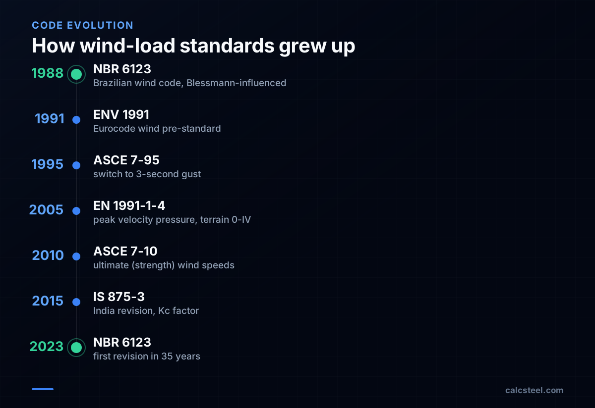
The codes engineers lean on today were not handed down complete. Brazil's NBR 6123 was first published in 1988, drawing heavily on the wind-engineering research of Joaquim Blessmann, whose work shaped the standard's coefficients. It then went 35 years without a full revision until ABNT published NBR 6123:2023 on December 20, 2023, a project coordinated by Prof. Acir Mercio Loredo-Souza with Prof. Andre Beck as secretary.
The American line moved differently. The ASCE 7-95 edition (approved 1995, issued 1996) switched the basic wind speed from fastest-mile to a 3-second gust, partly because the U.S. National Weather Service stopped collecting fastest-mile data, and introduced a modern gust-effect-factor formulation. Later, starting with ASCE 7-10, the wind basis moved from allowable-stress to ultimate (strength-level) wind speeds, with the ASD wind load then obtained by multiplying by 0.6. Europe consolidated its rules into EN 1991-1-4 (2005), built around a peak velocity pressure and terrain categories 0 to IV.
From a gust to a pressure coefficient
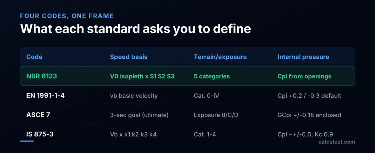
Despite different notations, every code follows the same logic. First, convert wind speed into a velocity (dynamic) pressure, q, which is roughly proportional to the square of a design wind speed adjusted for terrain roughness, height and a statistical return-period factor. In NBR 6123 this flows through factors S1, S2 and S3; in the 2023 revision the S3 statistical factor for ordinary (Group 1) buildings was raised from 1.10 to 1.11. Per the CAW commentary, that is about a 2% change in the factor itself. For cladding design the 2023 edition allows a 0.92 reduction factor on S3, returning cladding to roughly the level proposed for Group 4 in the 1988 version.
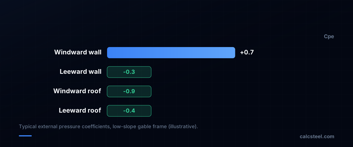
Then multiply q by pressure coefficients that describe how the building's shape redirects the flow. A windward wall sees positive pressure (push); leeward walls and most roof surfaces see suction (pull). These external coefficients, written Cpe, come from decades of wind-tunnel testing tabulated by building geometry and roof slope.
Internal pressure and enclosure classification: run it twice
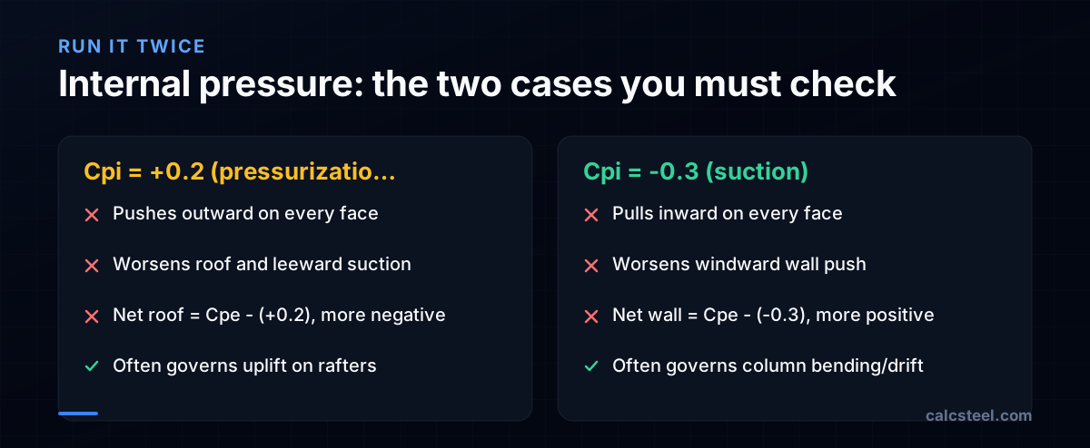
The trap that catches beginners is internal pressure. A building is not a sealed box: an open door or a large window changes the pressure inside, and that internal pressure pushes outward on every face simultaneously. The design quantity is therefore the net pressure: (Cpe - Cpi) x q. Because the opening regime (the enclosure classification) can swing the sign, codes require both an internal pressurization and an internal suction case.
In Eurocode practice, Cpi = +0.2 and -0.3 are the EN 1991-1-4 default values applied when the opening ratio of a face cannot be established. IS 875-3 instead derives Cpi from the percentage of openings (around +/-0.5 for typical industrial sheds) and applies a combination factor Kc of 0.9 for closed framed structures when wall, roof and internal pressures act together. ASCE 7 uses GCpi of +/-0.18 for enclosed buildings. The practical rule is blunt: both positive and negative internal pressures must be considered, and the governing one is whichever pairs worst with the external suction on the face you are checking.
How to apply a wind load case to a portal frame in CalcSteel
CalcSteel is a browser-native structural app: a React/TypeScript front end over a Python finite-element backend. The third-party desktop tools above (MasterSeries, RWIND, CADS) all automate load-case generation so geometry edits no longer mean redoing the wind by hand; CalcSteel follows the same automation principle, in the browser. Here is the click-by-click workflow:
- 1. Model the frame. In the editor, draw the two columns and the pitched rafter, set the steel profiles from the profile library, and fix the column bases as appropriate.
- 2. Create a wind load case per direction. Open the Loads panel and add a new load case; name it explicitly, for example WX+ (Cpi +0.2), WX+ (Cpi -0.3), and repeat for the opposite direction. Keep one case per (direction, internal-pressure sign) pairing.
- 3. Select the members. Pick the windward column, leeward column and each rafter segment so the pressure is applied to the right faces.
- 4. Apply the pressure as a line load. Enter the windward push, leeward suction and roof suction you computed from (Cpe - Cpi)q (see the next section for the conversion), using the load direction normal to each member.
- 5. Configure combinations. In the load-combination editor, pair the wind cases with dead and live load, including the uplift combination described below.
- 6. Run and check. Solve, then read the member verification against NBR 8800, AISC 360, Eurocode 3 or IS 800, and confirm base reactions for the uplift case.
Converting (Cpe - Cpi)q into the load input, and the uplift combination
This is the handoff most guides skip. Your code gives a surface pressure, p = (Cpe - Cpi) x q, in kPa (kN/m squared). A 2D portal frame is modelled with members, so each frame carries the wind from half the bay on each side: multiply the surface pressure by the tributary width (the frame spacing) to get a line load in kN/m. For example, p = 0.6 kPa on a frame at 6 m spacing gives 0.6 x 6 = 3.6 kN/m along that member. CalcSteel accepts the line load directly; if you model the cladding as a surface you can instead enter p in kPa and let the panel distribute it.
Watch the sign convention: enter push as pressure acting onto the face (positive, toward the member) and suction as pressure acting away from it (negative / outward). Roof suction is applied perpendicular to the rafter, wall pressure perpendicular to the column. For the combinations, a light frame is usually controlled not by gravity but by uplift. The case that decides column uplift, base plates and anchors is roughly 0.9 DL + 1.0 WL (uplift) in LRFD-style strength checks, or 0.6 DL + 0.6 WL in ASD, where the reduced dead load no longer holds the frame down against net roof suction. Always confirm whether your governing roof-uplift comes from the Cpi = +0.2 pairing, since positive internal pressure makes the net roof coefficient more negative.
Choosing a tool, and where CalcSteel fits
For wind on a portal frame you have real options. MasterSeries generates the frame and applies Eurocode 1 wind automatically across directions; Dlubal RWIND simulates the airflow and feeds surface loads into RFEM/RSTAB; CADS wind tools compute peak speeds split across sectors. These are mature desktop packages and are the right call for CFD-grade wind or large model libraries.
CalcSteel is the lightweight, browser-native alternative: a free plan plus Pro at US$24/month billed annually, 1,140+ steel profiles, and member checks for NBR 8800, AISC 360, Eurocode 3 and IS 800. What none of these tools removes is engineering judgment over the inputs: terrain category, return period, opening assumptions and enclosure classification are yours to defend, and the code-prescribed Cpe, Cpi and q remain values you compute and own. If you want to apply a wind load case, set the uplift combination and verify the steel without leaving the browser, build the frame in the editor and keep the worst pairing of external suction with internal pressure firmly in view.
Sources
- 1.Em vigor, a nova NBR 6123 - ABECE
- 2.Parametro S3 na NBR 6123 (1988/2023) - CAW
- 3.3-Second Gust Wind Speed Explained - ASCE 7 Design Wind Speed Basis
- 4.Wind Loads on Buildings: Ultimate versus Nominal - FDR Engineers
- 5.EN 1991-1-4:2005 Wind actions - Eurocodes (JRC)
- 6.IS 875-3 Wind Load Calculation Example - SkyCiv
- 7.Image: Dietmar Rabich — CC BY-SA 4.0 (Wikimedia Commons)
Try CalcSteel for free
Model, analyze and design steel structures in your browser. No install, no signup.
Open the 3D editor