What Purlin for a 6 m Span? The Section, and the Wind-Uplift Check That Decides It

"What purlin do I use for a 6 m span?" sounds like a table lookup, and for gravity it almost is. This deep-dive takes one real cold-formed C purlin, solves the 6 m span on the CalcSteel FEM engine for the gravity and wind-uplift load cases, checks every moment against wL squared over 8 by hand, and finds the twist: the section that sits at utilisation 0.41 under gravity fails at 1.13 under uplift, because the case that carries less moment loads the flange nobody braced.
Key takeaways
- A purlin for a 6 m span is not sized by its gravity moment. On this worked example the engine returns a peak gravity moment of 8.10 kN·m and the uplift moment is smaller at 4.86 kN·m, yet uplift governs and it is the check that fails.
- A single-span C 200x75x20x2.66 (fy 350 MPa) sits at utilisation 0.41 in gravity bending and 0.48 in deflection, so on gravity alone it looks finished with room to spare.
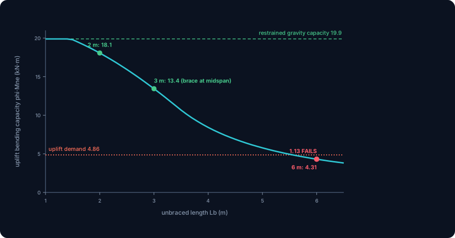
- Under wind uplift the compression flips to the bottom flange, which the roof sheeting does not brace. Over the full 6 m unbraced length the lateral-torsional capacity collapses from a restrained phi·My of 19.9 kN·m to a phi·Mne of just 4.31 kN·m, so the 4.86 kN·m demand pushes utilisation to 1.13 and the purlin is overstressed.
- The cheapest fix is not a heavier section, it is a line of anti-sag rods. Bracing the bottom flange at midspan cuts the unbraced length to 3.0 m, lifts phi·Mne to 13.4 kN·m and drops the uplift utilisation to 0.36. Third-point bracing (2.0 m) takes it to 0.27.
- The engine matches closed-form theory exactly: wL squared over 8 for moment, wL over 2 for shear and reaction, and 5wL to the fourth over 384EI for the mid-span deflection, so the demand you design to is equilibrium, not an estimate.
The wrong first question, and the right one
Ask an engineer "what purlin for a 6 m span" and the honest first answer is a question back: under what, and held how? For the gravity case it really is close to a table lookup, a thin folded section carrying a roof over 6 m is a well-trodden problem. The trap is that the purlin is almost never sized by the case you look up. It is sized by the case you have to remember, and on an exposed roof that case is wind uplift.
This article works one concrete purlin all the way through. A single-span cold-formed lipped channel, 6.0 m between rafters, carrying a light metal roof. We solve it on the CalcSteel finite element engine for gravity and for uplift, cross-check every moment against hand statics, then run the section capacity check for both cases. The result is the whole point of the piece: the section sits at utilisation 0.41 under the gravity combination, comfortable, and at 1.13 under uplift, overstressed. The case that carries the smaller moment is the one that fails, because it loads the flange the sheeting never braced.
The worked purlin: 6 m, cold-formed C, sheeting on top
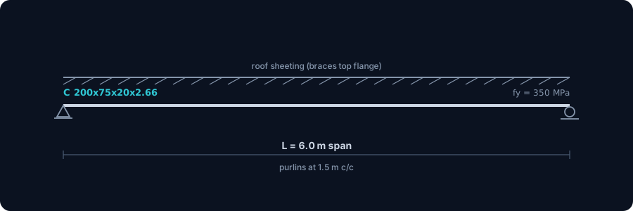
Here is the member we carry through the article. A simply supported single span of L = 6.0 m, pinned at one rafter and on a roller at the other, spaced at 1.5 m on centre across the roof so each purlin collects a 1.5 m wide strip of load. The section is a cold-formed lipped channel, a C 200x75x20x2.66 in steel grade fy = 350 MPa, one of the standard NBR 6355 purlin sizes and a natural first pick for a 6 m bay.
Two facts about that section decide everything downstream. First, it is thin, 2.66 mm of folded strip, which is what makes it light and cheap, and also what makes it prone to buckling long before the steel yields. Second, it is open and singly symmetric, so it has very little torsional and warping stiffness. When the compression flange is not held, the section would rather twist sideways than keep bending, and that is lateral-torsional buckling. The roof sheeting fixed to the top flange braces it against exactly that, but only the top flange, and only while the top flange is the one in compression. Hold on to that condition.
Three loads, two combinations, and the sign that matters
Three load cases reach this purlin, and because they do not act at full value together we keep them separate and combine them afterward. Taken over the 1.5 m spacing, each area pressure becomes a line load along the purlin:
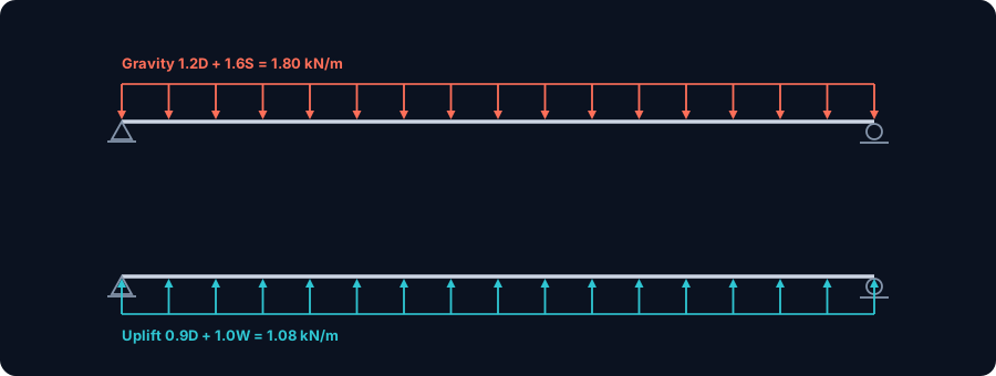
- Dead load D, the sheeting, fixings and the purlin itself, about 0.20 kN/m2. Over 1.5 m that is 0.30 kN/m down.
- Snow or roof imposed load S, about 0.60 kN/m2, giving 0.90 kN/m down.
- Wind load W, which on a low-slope roof is dominated by suction, the net pressure pulls up. Taken as about 0.90 kN/m2 of net uplift for an exposed bay, it is 1.35 kN/m up, the only load that lifts.
Two strength (LRFD) combinations bracket the design. The gravity maximum is 1.2D + 1.6S = 1.80 kN/m pressing down. The uplift combination pairs minimum dead load with full wind so nothing helps resist the lift: 0.9D + 1.0W, which nets to 1.08 kN/m acting up. Notice the uplift line load is smaller in magnitude than the gravity one, 1.08 against 1.80. If moment were the whole story, gravity would win and we would be done. It is not, and that is the article.
Gravity first, and a hand check that matches to the digit
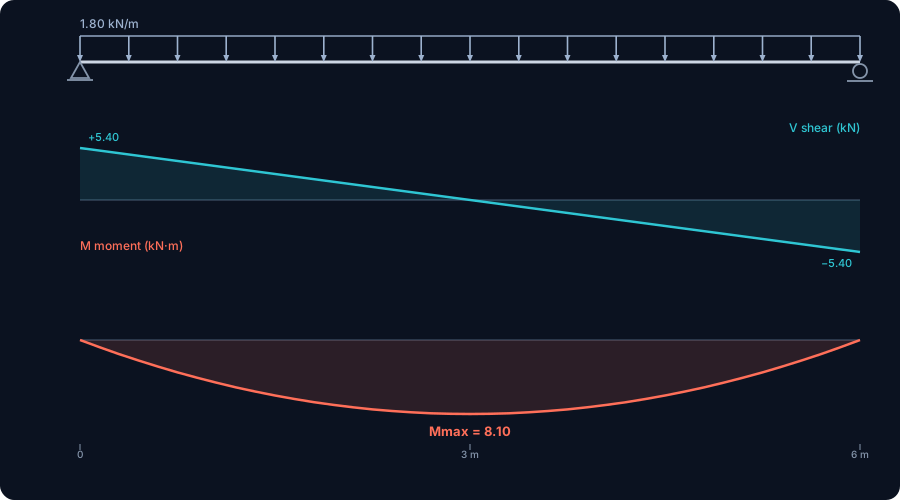
Drop the purlin into the CalcSteel engine, apply the gravity line load of 1.80 kN/m, and read the diagram. For a simply supported span under a uniform load the answer is the most familiar in structural engineering, and the engine returns it exactly:
- Peak bending moment at midspan, M = 8.10 kN·m, matching wL squared over 8 = 1.80 x 6.0 squared / 8 = 8.10 to four decimals.
- Peak shear at the supports, V = 5.40 kN, matching wL over 2 = 1.80 x 6.0 / 2 = 5.40.
- Each reaction 5.40 kN down into the rafter.
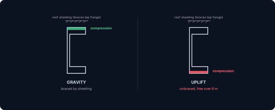
Under this gravity moment the top flange is in compression and the bottom flange in tension. The sheeting is screwed to that top flange, so the compression flange is continuously braced, it cannot buckle sideways, and the section can develop its full bending capacity. This is the easy, well-behaved case, and it is exactly the one a span table is built for. It is also, as we are about to see, not the one that sizes the purlin.
Try it: put your own 6 m span in
Before the uplift twist, get a feel for the gravity demand yourself. The calculator below is the CalcSteel beam calculator. Enter a span of 6 m, a uniform load of 1.80 kN/m and simple supports, and it returns the reactions, the shear and bending-moment diagrams and the mid-span deflection, the same numbers the engine gave above. Then try the uplift value of 1.08 kN/m and watch the moment fall to 4.86 kN·m. The next sections show why that smaller number is the dangerous one.
Max moment
45 kN·m
Max shear
30 kN
Max deflection
10.55 mm
= L/569
Bending stress σ
84.4 MPa
σ = M/Sx
Utilization
44.0%
NBR 8800 · δ ≤ L/250
Geometry & supports
Section
Ix 7999 cm⁴ · Sx 533 cm³ · 42.2 kg/m
Point loads (↓ positive)
None — add as many as you need.
Distributed loads (uniform or trapezoidal)
Model sketch
Diagrams — free PNG / SVG / CSV export, no watermark
Step-by-step — the calculation memory of YOUR beam
IPE 300 · L = 6 m · fy = 250 MPa
1. Reactions (equilibrium of the solved FEM model)
ΣFy = 0 · ΣM = 0
R_A = 30 kN · R_B = 30 kN
2. Peak shear (read from the SFD)
Vmax = |V(x)|max
Vmax = -30 kN @ x = 6 m
3. Peak moment (read from the BMD)
Mmax = |M(x)|max
Mmax = 45 kN·m @ x = 3 m
4. Peak deflection
EI = 15998 kN·m² (E = 200 GPa)
δmax = 10.55 mm @ x = 3 m = L/569
5. Elastic bending stress
σ = Mmax / Sx = 45.00 × 10³ / 533.3
σ = 84.4 MPa
6. Bending check — both codes, side by side
NBR 8800: σ ≤ fy/1.10 = 227.3 MPa · AISC 360: σ ≤ 0.90·fy = 225 MPa
NBR 37.1% PASS · AISC 37.5% PASS
7. Deflection check (serviceability — code-independent)
δ ≤ L/250 = 24 mm
10.55 mm / 24 mm = 44.0% PASS
Recomputed live from the current inputs by the direct-stiffness FEM engine — change any load and every step updates. Reproduce it by hand with the formulas in the sections below.
Lightest catalog profiles that pass (974 flexural candidates · NBR 8800)
| Profile | Std | Weight | Total steel | σ util | δ util | |
|---|---|---|---|---|---|---|
| W310x21 | AISC | 21 kg/m | 126 kg | 83% | 98% | |
| VS 300x23 | BR | 22.6 kg/m | 136 kg | 71% | 84% | |
| U 300x90x6.3 | BR | 23.1 kg/m | 139 kg | 82% | 98% | |
| U 300x100x6.3 | BR | 24.1 kg/m | 145 kg | 77% | 91% | |
| VS 250x25 | BR | 24.6 kg/m | 148 kg | 70% | 100% |
Elastic bending (σ = M/Sx vs fy/γa1, γa1 = 1.10 — NBR 8800) + deflection screening of the full flexural catalog. Lateral-torsional buckling, shear and local buckling are NOT checked here — run the full NBR 8800 / AISC 360 verification in the 3D editor.
Picking the section, and why gravity says yes
Now size the C 200x75x20x2.66 for gravity. Its section properties, the same values the CalcSteel catalog carries, are the input to every check:
| Property | Value | Property | Value |
|---|---|---|---|
| Area A | 10.16 cm2 | Strong-axis modulus Sx | 63.15 cm3 |
| Inertia Ix | 631.5 cm4 | Weak-axis inertia Iy | 78.28 cm4 |
| Torsion constant J | 0.240 cm4 | Warping constant Cw | 4267 cm6 |
Bending, gravity. With the compression flange braced by the sheeting, lateral-torsional buckling is switched off and the section reaches its yield moment, My = Fy x Sx = 350 x 63.15 x 10 cubed = 22.10 kN·m. With the resistance factor phi = 0.90 that is a design capacity of 19.9 kN·m. Against the 8.10 kN·m demand the utilisation is 8.10 / 19.9 = 0.41. Comfortable. (The full cold-formed check trims this a little for local buckling of the thin plate elements, but not enough to change the story.)
Deflection. Under the service gravity load D + S = 1.2 kN/m the engine reports a mid-span sag of 16.0 mm, matching the hand formula 5wL to the fourth over 384EI to four decimals. The common purlin limit of L/180 allows 6000 / 180 = 33.3 mm, so deflection sits at 0.48. Shear, at 5.40 kN against a web capacity many times larger, is nowhere near. Read the gravity column and the purlin looks finished: bending 0.41, deflection 0.48, shear trivial. A span table would stop here and hand you the C200.
Wind uplift moves the compression to the wrong flange
Now run the uplift combination, 1.08 kN/m acting up. The engine returns a peak moment of 4.86 kN·m (wL squared over 8 = 1.08 x 36 / 8, matched exactly) and a shear of 3.24 kN. Both are smaller than the gravity values. The reactions also reverse: instead of 5.40 kN pressing into the rafter, the support now pulls 3.24 kN up, which is why the purlin cleats and their fasteners have to be detailed for uplift, a whole separate failure the gravity case never hints at.
But the number that matters is not the moment, it is which flange carries it. Under gravity the top flange was in compression and the sheeting braced it. Under uplift the moment reverses, so the bottom flange goes into compression, and nothing braces the bottom flange. It hangs free below the sheeting over the entire 6 m span. The section is now a long, thin, unrestrained compression element that would rather twist sideways than keep bending. That is lateral-torsional buckling, and it changes the capacity by an order of magnitude, even though the demand went down.
The uplift check: capacity collapses, and the section fails
Put a number on it. The bottom flange is unbraced over the full Lb = 6.0 m, so we compute the elastic lateral-torsional buckling moment of the section from its own stiffness, Mcr, and map it to a capacity with the AISI Direct Strength Method global-buckling curve. With Iy = 78.28 cm4, J = 0.240 cm4 and Cw = 4267 cm6, and a moment-gradient factor Cb = 1.13 for a uniformly loaded simple span:
| Unbraced length Lb | Mcr | Capacity phi·Mne | Uplift utilisation |
|---|---|---|---|
| 6.0 m (bare span) | 4.79 kN·m | 4.31 kN·m | 1.13, fails |
| 3.0 m (brace at midspan) | 15.7 kN·m | 13.4 kN·m | 0.36 |
| 2.0 m (third-point braces) | 33.6 kN·m | 18.1 kN·m | 0.27 |
Read the top row. Over 6 m the elastic buckling moment is only 4.79 kN·m, so far below the yield moment of 22.10 that the section buckles long before it yields, and the design capacity is 4.31 kN·m. Against the 4.86 kN·m uplift demand the utilisation is 1.13. The purlin is overstressed. The exact same section that sat at 0.41 in gravity bending is unsafe under a load case that carries 40 percent less moment. Nothing about the demand grew, the capacity collapsed, because the compression flange lost its brace.
The fix is a brace, not a bigger purlin
The instinct after a failed check is to go up a section. Here that is the expensive lever and almost the wrong one, because the uplift check is a buckling check and buckling capacity is governed by the unbraced length, not mainly by the section size. Add a single line of anti-sag rods (bridging) at midspan and the unbraced length of the bottom flange drops from 6.0 m to 3.0 m. That alone lifts the capacity from 4.31 to 13.4 kN·m and the uplift utilisation from 1.13 to 0.36. The failing purlin passes, on the same C200, for the price of a few rods and a coupler.
Line the whole design up and the shape of the problem is clear:
| Check | Demand | Capacity | Utilisation |
|---|---|---|---|
| Gravity bending (braced) | 8.10 kN·m | 19.9 kN·m | 0.41 |
| Deflection (service, L/180) | 16.0 mm | 33.3 mm | 0.48 |
| Uplift bending, bare 6 m | 4.86 kN·m | 4.31 kN·m | 1.13, fails |
| Uplift bending, midspan brace | 4.86 kN·m | 13.4 kN·m | 0.36 |
Gravity and deflection are both under 0.5, so the section has plenty of margin where a table would look. The only failing check is the one a table cannot show you, and it is fixed not with steel but with a brace. Bridging at midspan, or a proven diaphragm connection to the sheeting that actually restrains the bottom flange, is the standard detail. Go up a section only if the geometry rules out the brace.
What the codes ask, on three continents
The workflow, gravity demand then uplift demand then a capacity that depends on bracing, is the same everywhere. The packaging differs.
- United States (AISI S100). The Direct Strength Method computes the member from its elastic buckling moments, and the global (lateral-torsional) curve is the one that collapses under uplift. AISI also credits sheeting restraint through the R-factor procedure of AISI S908, calibrated by physical base tests.
- Europe (EN 1993-1-3). Eurocode models the sheeting as an explicit rotational spring restraining the purlin, so the free-flange check under uplift is done on a flange elastically held by the roof, an approach traced to Peköz and Soroushian. The load combination with permanent action favourable and wind leading is the uplift case.
- Brazil (NBR 14762 with NBR 6355 sections). The Brazilian cold-formed standard follows the same effective-section and global-buckling philosophy, on the NBR 6355 profile catalog this C section comes from, with serviceability for purlins commonly at L/180.
Different symbols, one idea. Every one of these codes gives you the uplift combination alongside the gravity one, and every one drops the capacity when the compression flange is unbraced. The CalcSteel engine checks the member against AISC 360, Eurocode 3 and NBR 8800 from the same forces, so the governing case is computed rather than remembered. For the load side, our note on load combinations and on wind loads covers where the 1.08 kN/m came from.
Common mistakes and FAQ
"Just check the gravity bending, it is the biggest moment." The biggest moment is not the governing check. On this purlin gravity bending is 0.41 and uplift bending is 1.13, on the same section, because uplift loads the unbraced flange. Magnitude of moment does not tell you which case wins.
"The sheeting braces the purlin, so buckling is not an issue." The sheeting braces the top flange. Under uplift the compression moves to the bottom flange, which the sheeting does not hold. That is the entire reason uplift governs. A purlin can be fully braced for gravity and completely unbraced for uplift at the same time.
"Wind uplift is smaller than gravity, so gravity governs." Smaller in load and in moment, yes. But it acts through a much smaller capacity, because the free bottom flange over 6 m buckles at a fraction of the yield moment. A case is governed by demand relative to its own capacity, and the two capacities here differ by more than four to one.
"Go up a section to fix the uplift failure." Usually the wrong lever. Buckling capacity depends on unbraced length, so a line of anti-sag rods buys more capacity, more cheaply, than a heavier gauge. Fix the length before you add the steel.
"C or Z, does it matter here?" For a single simple span the two behave similarly, and both fail this uplift check bare. Z sections shine on continuous multi-span roofs because they lap over the supports and share the moment. For one 6 m simple span, the bracing decision matters far more than the C-versus-Z decision.
From a span number to the deciding case
So, what purlin for a 6 m span? Not a name off a table. On this roof a C 200x75x20x2.66 is the right family and gauge, but only once you have run the case the table cannot: wind uplift, which loads the unbraced bottom flange and drops the bending capacity from 19.9 kN·m to 4.31, failing a section that gravity passed at 0.41. The section is an output of the governing check, and for an exposed purlin that check is uplift.
The demand side is not guesswork, it is equilibrium: on this span the engine reproduced wL squared over 8, wL over 2 and 5wL to the fourth over 384EI to four decimals. The capacity side is where judgement lives, and it turns on one detail, whether the bottom flange is braced. CalcSteel runs the load cases, forms the combinations and reports the governing bending, shear and deflection check for the section at once, so the uplift case is computed, not forgotten. Model your own 6 m purlin in the editor, add the uplift combination, and watch the utilisation cross 1.0. For the underlying mechanism, our guides to lateral-torsional buckling and purlin sizing cover the buckling mode and the broader design loop this worked example lives inside.
Sources
- 1.AISI S100, North American Specification for the Design of Cold-Formed Steel Structural Members (Direct Strength Method, lateral-torsional buckling)
- 2.AISI S908, Base Test Method for Purlins Supporting a Standing Seam Roof System (sheeting restraint R-factors)
- 3.EN 1993-1-3, Eurocode 3: Design of steel structures, Part 1-3: Cold-formed members and sheeting (rotational restraint, free-flange under uplift)
- 4.ABNT NBR 14762, Dimensionamento de estruturas de aco constituidas por perfis formados a frio, and NBR 6355 (cold-formed profile catalog)
- 5.AISI D111, Design Guide for Cold-Formed Steel Purlin Roof Framing Systems
Try CalcSteel for free
Model, analyze and design steel structures in your browser. No install, no signup.
Open the 3D editor