What Mezzanine Floor Beam? Sizing for a Real Live Load Where Deflection Controls
A mezzanine floor beam is one of the most common jobs a steel designer picks up, and it is the classic case where strength is the easy check and stiffness is the one that actually sizes the section. Here is a full worked example: a 6 m storage mezzanine beam under a real 5.0 kN/m² live load, taken through the strength check and the deflection check side by side. The section that passes bending at 90% utilisation still sags 27 mm where the code allows 16.7, so the beam jumps two full sizes on deflection alone. Every number is computed by CalcSteel's real FEM engine and reconciled with hand calculation.
Key takeaways
- For a floor beam, deflection usually governs, not strength. In the worked case an IPE 240 passes bending at 90% utilisation yet deflects 27.1 mm under live load, well past the L/360 limit of 16.7 mm, so it is rejected on serviceability alone.
- The live load is a code table lookup, not a guess. A storage or commercial mezzanine commonly carries 4.0 to 6.0 kN/m² (light storage is 125 psf in the IBC), far above a home floor's 1.5 to 2.0 kN/m², and the higher the live load the harder deflection bites.
- Two serviceability limits do the sizing: L/360 under live load (16.7 mm here) and L/240 total (25 mm). Both are checked with unfactored (characteristic) loads, unlike the factored strength check.
- Worked and engine-checked: the demand is M = 56.25 kN·m and V = 37.5 kN under the 12.5 kN/m characteristic line load, reproduced by the FEM engine to three decimals. The required second moment of area for L/360 is 6328 cm⁴, which rules out IPE 270 and lands on IPE 300.
- Deflection scales with 1/I while bending strength scales with the section modulus, so the fix is depth, not grade. Going to a higher steel grade does nothing for deflection: the IPE 300 that satisfies L/360 is only 53% utilised in bending, carrying 37% more steel than strength alone would have asked for.
The question, and why the answer is about stiffness
You have a mezzanine to frame, a raised steel floor tucked inside a warehouse, a shop, or an office, and the practical question is blunt: what beam? Which section carries the floor, and how do you know it is the right one? The instinct is to reach for a bending check, find the section whose moment capacity beats the applied moment, and call it sized. For a mezzanine floor beam that instinct picks the wrong section almost every time.
The reason is that a floor is judged twice. It has to be strong enough not to fail, and it has to be stiff enough not to sag, bounce, or crack the finishes below it. These are two different limit states with two different governing quantities, and for the short, heavily loaded spans that mezzanines live in, the stiffness check wins. A beam can pass bending with room to spare and still be unacceptable because it deflects too far. This article works one real mezzanine beam all the way through both checks so you can see exactly where, and by how much, deflection takes over the decision.
The worked scenario, pinned down
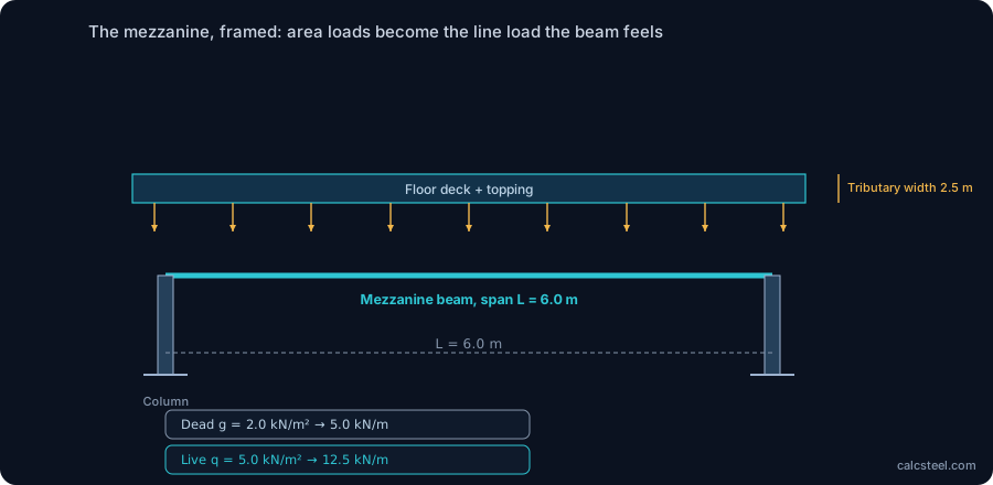
Keep it concrete. The mezzanine is a light storage and general commercial floor, framed with simply supported steel beams spanning L = 6.0 m, spaced at 2.5 m centres, in grade S355 steel. A steel deck with a thin topping spans between the beams and, once fixed, provides continuous lateral restraint to the top (compression) flange, so lateral-torsional buckling does not reduce the bending capacity. That is a normal, defensible mezzanine build.
Each beam carries a 2.5 m wide tributary strip of floor, so the area loads convert straight to line loads on the beam:
- Superimposed dead load (deck, topping, finishes, services): gk = 2.0 kN/m², giving 5.0 kN/m on the beam, plus the beam's own self-weight.
- Live (imposed) load: qk = 5.0 kN/m², giving 12.5 kN/m on the beam.
Those two numbers, 5.0 and 12.5 kN/m, drive everything that follows. The live load in particular deserves its own step, because it is not something you invent.
Step one: the live load is a code lookup, not a guess
The single most important input to a mezzanine floor beam is the live load, and it is fixed by occupancy in a code table. Get it wrong and every downstream number is wrong. The values are not small, and they climb fast with use:
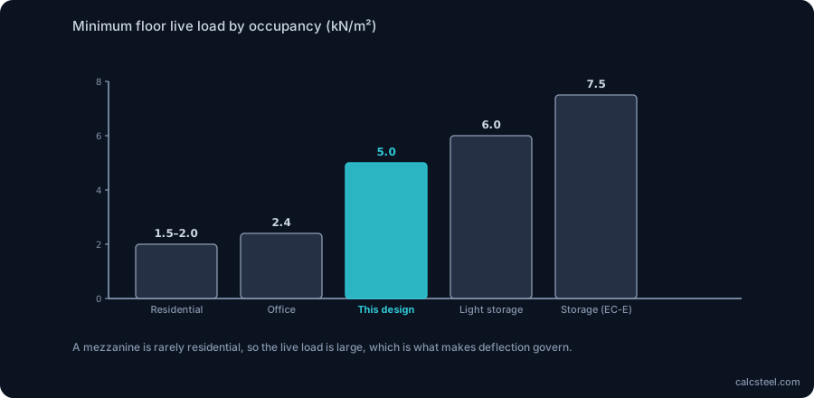
- Residential floors sit at roughly 1.5 to 2.0 kN/m² (about 40 psf in the IBC). This is the light end, and it is what our companion piece on the residential mezzanine works through.
- Offices read about 2.4 kN/m² (50 psf), and the IBC adds a 15 psf partition allowance when the specified live load is under 80 psf, whether or not walls are built.
- Light storage, the most common industrial mezzanine use, jumps to 125 psf, about 6.0 kN/m², and Eurocode 1 puts storage areas (Category E) at 7.5 kN/m² and up.
Our worked value, 5.0 kN/m², is a representative real commercial and light-storage load, several times a home floor. This matters for the punchline: deflection is proportional to load, so a mezzanine's high live load is exactly what pushes the serviceability check ahead of strength. The same beam under a residential 2.0 kN/m² might pass deflection comfortably; under a storage 5.0 kN/m² it does not.
The two gates: strength and serviceability
Every floor beam has to clear two independent gates, and they use different loads and ask different questions.
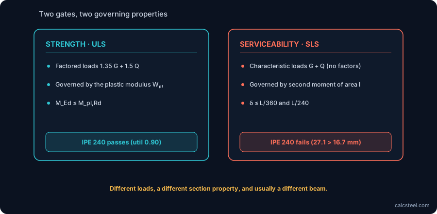
Strength (ultimate limit state). Can the section carry the factored load in bending and shear without yielding or buckling? Loads are amplified by partial factors (1.35 dead and 1.5 live in Eurocode, 1.2 dead and 1.6 live in AISC LRFD), and the section's moment resistance must beat the resulting design moment. This is the check people mean by 'will it hold?'.
Serviceability (deflection). Under the unfactored (characteristic) load, does the beam stay within a deflection limit set so that finishes do not crack, doors do not stick, and the floor does not look or feel wrong? The classic limits, used by the IBC's Table 1604.3 and mirrored across codes, are L/360 under live load and L/240 total. For our 6 m span:
- Live-load limit: L/360 = 6000/360 = 16.7 mm
- Total-load limit: L/240 = 6000/240 = 25.0 mm
The trap is that these two gates do not move together. Strength depends on the section modulus; deflection depends on the second moment of area and, critically, on the span to the fourth power. On a short mezzanine span with a big live load, a section can stroll through strength and slam into the deflection wall. The only way to know which gate governs is to check both, so that is what we do next, on the same beam.
Step two: size by strength, and it looks finished
Start where the instinct sends you, at strength. Factor the loads (Eurocode 1.35 dead, 1.5 live), including a first guess at self-weight:
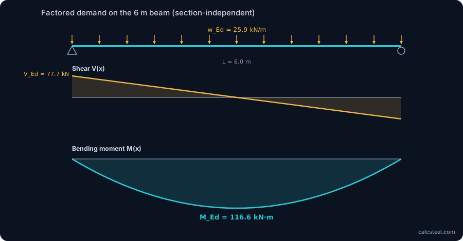
wEd = 1.35 · (5.0 + 0.30) + 1.5 · 12.5 = 25.9 kN/m
For a simply supported beam the design moment and shear are the textbook results, and because they come only from statics they do not depend on the section at all:
MEd = wEdL²/8 = 25.9 · 6²/8 = 116.6 kN·m
VEd = wEdL/2 = 77.7 kN
Now find a section that carries it. An IPE 240 in S355 has a plastic modulus Wpl,y = 366.6 cm³, so with the deck restraining the compression flange its bending resistance is Mpl,Rd = fy·Wpl,y = 355 · 366.6/1000 = 130.1 kN·m. That beats the 116.6 kN·m demand at a utilisation of 0.90. Shear is nowhere close: the IPE 240 shear resistance is about 391 kN against a 77.7 kN demand. On strength, the IPE 240 passes, and at 90% it even looks efficient. A designer who stops here writes down IPE 240 and moves on. That is the mistake.
Step three: the deflection check rejects it
Now the second gate. Deflection uses the characteristic loads (no factors), and the live-load deflection of a simply supported beam under a uniform load is:
δ = 5·q·L⁴ / (384·E·I)
with q = 12.5 kN/m (the live line load), L = 6000 mm, E = 200 000 MPa (200 GPa, the value CalcSteel's engine uses, equal to the AISC 29 000 ksi), and I the beam's second moment of area. For the IPE 240, I = 3892 cm⁴, and the arithmetic gives:
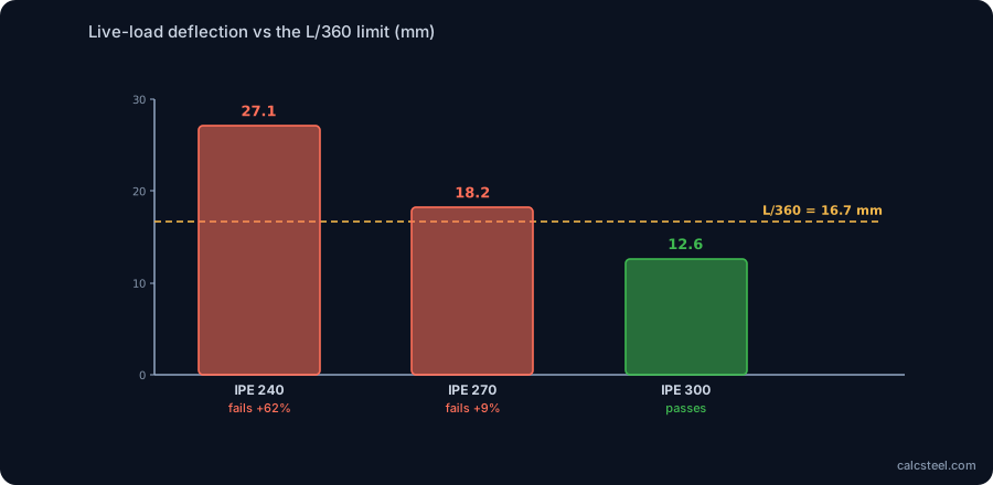
δlive = 27.1 mm against a limit of 16.7 mm
The IPE 240 deflects 62% past its live-load limit. The total-load deflection is worse still at 38.6 mm against the 25 mm cap. The section that passed bending at 90% utilisation fails serviceability outright, and it is not close. This is the whole story of the mezzanine floor beam in one line: strength said yes, deflection said no.
So go up a size. An IPE 270 (I = 5790 cm⁴) is a much stiffer beam, and its bending utilisation drops to a comfortable 0.68. Its live deflection? 18.2 mm, still over the 16.7 mm limit by 9%. The tempting middle section, the one that feels like it should be plenty, misses too. You have to reach an IPE 300 (I = 8356 cm⁴) before the live deflection lands at 12.6 mm, inside the limit, with the total deflection at 18.1 mm, comfortably under 25 mm. The IPE 300 is the answer, and its bending utilisation is a mere 0.53.
The section jumped two sizes, and 37% in steel
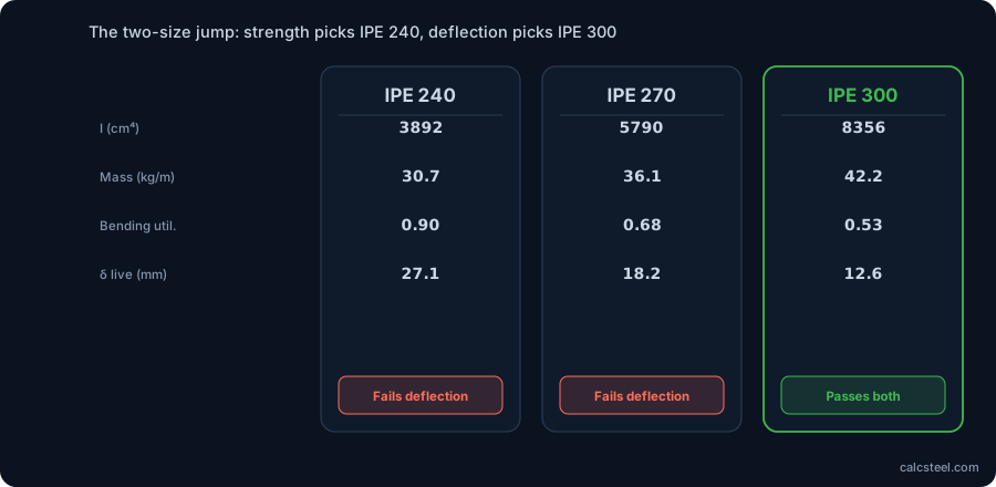
Line the three candidates up and the cost of serviceability is plain. Strength alone would have bought an IPE 240. Deflection forced an IPE 300, two sizes deeper, at 42.2 kg/m against 30.7 kg/m, about 37% more steel for the same beam. None of that extra material is doing strength work: the final section is barely half utilised in bending.
| Section | I (cm⁴) | Wpl,y (cm³) | Mass (kg/m) | Bending util. | δlive (mm) | L/360 = 16.7 mm |
|---|---|---|---|---|---|---|
| IPE 240 | 3892 | 366.6 | 30.7 | 0.90 | 27.1 | Fails (+62%) |
| IPE 270 | 5790 | 484.0 | 36.1 | 0.68 | 18.2 | Fails (+9%) |
| IPE 300 | 8356 | 628.4 | 42.2 | 0.53 | 12.6 | Passes |
Reading a table like this is the actual work of sizing a floor beam. The bending-utilisation column tells you the beam is over-designed for strength; the deflection column tells you why you cannot use anything lighter. If you only ever looked at the first, you would ship an IPE 240 and get a floor that sags visibly and feels alive underfoot.
Why deflection wins, and why grade cannot save you
The reason deflection governs a mezzanine floor beam is built into the two formulas. Bending strength is proportional to the section modulus and to the yield strength fy. Deflection is proportional to 1/I, the reciprocal of the second moment of area, and to L⁴. Those are different levers.
The cleanest way to see it is to solve the deflection limit for the stiffness you need. Setting δ = L/360 and rearranging:
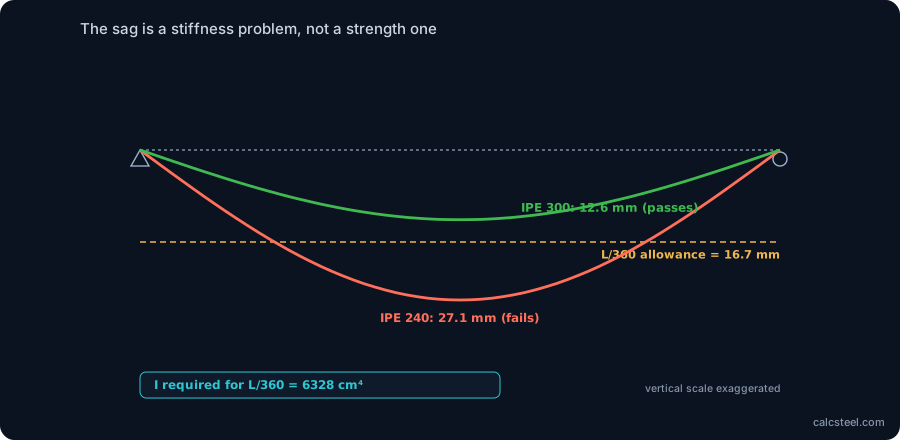
Ireq = 5·q·L⁴ / (384·E·(L/360)) = 6328 cm⁴
That single number decides the beam. The IPE 270 offers 5790 cm⁴ and is short; the IPE 300 offers 8356 cm⁴ and clears it. No strength calculation was involved.
This also explains the most common wrong instinct: upgrading the steel grade does nothing for deflection. Going from S275 to S355, or S355 to S460, raises fy and so raises bending capacity, but the modulus of elasticity E is essentially the same for all structural steels (about 200 GPa), and deflection depends on E and I, not on fy. A stronger steel lets you use a lighter section for strength, which makes the deflection problem worse. When stiffness governs, the only real levers are a deeper section (bigger I), a shorter span or an extra support (L⁴ is brutal), composite action with the concrete topping (which can lift the effective I sharply), or pre-cambering the beam to offset the dead-load portion. Reaching for a higher grade is the one move that cannot help.
The engine check: same beam, same numbers
Everything above was hand calculation. To make it auditable we rebuilt the identical beam in CalcSteel's finite-element engine, the real shipping solver, and let it compute the demand from first principles by assembling and solving K·d = F. Under the 12.5 kN/m characteristic live load it returns support reactions of 37.500 kN each, a maximum shear of 37.500 kN, and a mid-span moment of 56.250 kN·m, matching the closed-form wL/2 and wL²/8 to three decimals. Scale the same model to the factored load and the design moment lands on the 116.6 kN·m used above.
The mid-span deflection comes out at 13.0 mm for the IPE 300, right beside the 12.6 mm hand value. The small gap is honest and worth naming: the engine derives the second moment of area from the profile's actual geometry, which sits a few percent below the rounded catalogue table value we used by hand, so the engine reads marginally more flexible. It moves the deflection the safe way, and it does not change a single verdict: IPE 240 and IPE 270 still fail L/360, IPE 300 still passes. That is the point of checking both by hand and by machine, the two agree, and where they differ you understand exactly why.
Try it: size your own mezzanine beam
The calculator below is the same FEM engine, running in your browser. Set a 6 m simply supported beam, apply a 12.5 kN/m uniform load, and read the bending moment and the deflection together, then swap the section and watch the deflection move while the moment stays put. Push the span from 6 m toward 7 or 8 m and see how fast the L⁴ term drives the deflection, and therefore the required depth, up. It is free, and there is no login for the analysis.
Sizing a beam is a loop, load, section, check, repeat, and a live model collapses that loop to a single edit. When you want to see the second moment of area a section actually gives you, the moment of inertia calculator pairs naturally with this one.
Max moment
45 kN·m
Max shear
30 kN
Max deflection
10.55 mm
= L/569
Bending stress σ
84.4 MPa
σ = M/Sx
Utilization
44.0%
NBR 8800 · δ ≤ L/250
Geometry & supports
Section
Ix 7999 cm⁴ · Sx 533 cm³ · 42.2 kg/m
Point loads (↓ positive)
None — add as many as you need.
Distributed loads (uniform or trapezoidal)
Model sketch
Diagrams — free PNG / SVG / CSV export, no watermark
Step-by-step — the calculation memory of YOUR beam
IPE 300 · L = 6 m · fy = 250 MPa
1. Reactions (equilibrium of the solved FEM model)
ΣFy = 0 · ΣM = 0
R_A = 30 kN · R_B = 30 kN
2. Peak shear (read from the SFD)
Vmax = |V(x)|max
Vmax = -30 kN @ x = 6 m
3. Peak moment (read from the BMD)
Mmax = |M(x)|max
Mmax = 45 kN·m @ x = 3 m
4. Peak deflection
EI = 15998 kN·m² (E = 200 GPa)
δmax = 10.55 mm @ x = 3 m = L/569
5. Elastic bending stress
σ = Mmax / Sx = 45.00 × 10³ / 533.3
σ = 84.4 MPa
6. Bending check — both codes, side by side
NBR 8800: σ ≤ fy/1.10 = 227.3 MPa · AISC 360: σ ≤ 0.90·fy = 225 MPa
NBR 37.1% PASS · AISC 37.5% PASS
7. Deflection check (serviceability — code-independent)
δ ≤ L/250 = 24 mm
10.55 mm / 24 mm = 44.0% PASS
Recomputed live from the current inputs by the direct-stiffness FEM engine — change any load and every step updates. Reproduce it by hand with the formulas in the sections below.
Lightest catalog profiles that pass (974 flexural candidates · NBR 8800)
| Profile | Std | Weight | Total steel | σ util | δ util | |
|---|---|---|---|---|---|---|
| W310x21 | AISC | 21 kg/m | 126 kg | 83% | 98% | |
| VS 300x23 | BR | 22.6 kg/m | 136 kg | 71% | 84% | |
| U 300x90x6.3 | BR | 23.1 kg/m | 139 kg | 82% | 98% | |
| U 300x100x6.3 | BR | 24.1 kg/m | 145 kg | 77% | 91% | |
| VS 250x25 | BR | 24.6 kg/m | 148 kg | 70% | 100% |
Elastic bending (σ = M/Sx vs fy/γa1, γa1 = 1.10 — NBR 8800) + deflection screening of the full flexural catalog. Lateral-torsional buckling, shear and local buckling are NOT checked here — run the full NBR 8800 / AISC 360 verification in the 3D editor.
The third gate a mezzanine can hide: vibration
Strength and deflection are the two gates that size the beam here, but a slender steel floor has a third check that occasionally overrides both: walking vibration. A beam that passes strength and even deflection can still feel like a trampoline, because the floor's natural frequency can sit near the rhythm of footsteps and resonate. That is a comfort (serviceability) issue, governed by AISC Design Guide 11, and for a long, lightly damped mezzanine it can dictate a still deeper section than L/360 alone.
It does not usually govern a 6 m storage floor loaded to 5 kN/m² like this one, where deflection is already forcing an IPE 300, but it is the reason you cannot fully automate a mezzanine to a single moment check. We work the vibration check in detail, alongside the load tables and deflection, in the companion residential mezzanine article, and the broader picture of what actually limits a beam is in the five checks that decide a steel beam's capacity.
Common mistakes and FAQ
Sizing on bending alone. The headline error, and the whole subject of this article. A moment check picks the lightest section that holds; for a floor beam that section is routinely too flexible. Always run deflection, on characteristic loads, before you commit.
Checking total deflection but not live. The L/240 total limit and the L/360 live limit are separate, and for imposed-load-dominated floors the L/360 live check is usually the tighter one. Do both.
Guessing the live load. It is a code table entry keyed to occupancy, and a storage mezzanine is not an office is not a home. Missing the partition allowance, or reading a residential number for a commercial floor, quietly under-loads the whole design.
Reaching for a higher steel grade to fix a deflection failure. It cannot work: E is the same for all structural steels, so a stronger grade changes strength, not stiffness. Add depth, add a support, go composite, or camber.
Does the deck really give lateral restraint? Only once it is fixed to the beam and able to act as a diaphragm. If the compression flange is unrestrained during construction or by a bare deck, lateral-torsional buckling can cut the bending capacity and must be checked separately.
Can composite action save the section? Often, yes. Connecting the beam to the concrete topping with shear studs can raise the effective second moment of area enough to bring the deflection back inside the limit without going deeper, which is exactly why composite mezzanine beams are so common.
Is IPE the only choice? No. The same logic sizes a UB, a W-section, or a built-up member; the profile family changes the exact numbers, not the conclusion that stiffness governs. Search your own catalogue for the shallowest section that clears Ireq.
Key takeaways
A mezzanine floor beam is the textbook case where the strength check is the easy one and the deflection check does the real sizing.
- Take the live load from the code table, not intuition: a storage or commercial mezzanine carries 4 to 6 kN/m² or more, several times a home floor, which is what pushes deflection ahead of strength.
- Check two serviceability limits on characteristic loads: L/360 under live (16.7 mm here) and L/240 total (25 mm), separately from the factored strength check.
- In the worked case the IPE 240 passes bending at 90% utilisation but deflects 27.1 mm, 62% past L/360; even the IPE 270 misses by 9%; the IPE 300 is the section deflection demands.
- The controlling number is the required stiffness, Ireq = 6328 cm⁴ for L/360, verified against the FEM engine's M = 56.25 kN·m and V = 37.5 kN to three decimals.
- When stiffness governs, add depth, span, support, composite action, or camber. A higher steel grade raises strength but not E, so it cannot fix a deflection failure, and often makes it worse.
Sources
- 1.IBC 2018 Section 1607 Live Loads (ICC)
- 2.IBC Table 1604.3 Deflection limits (L/360 live, L/240 total)
- 3.EN 1991-1-1 Eurocode 1: Imposed loads on buildings (Categories A to E)
- 4.EN 1993-1-1 Eurocode 3: Design of steel structures (serviceability, resistance)
- 5.AISC Design Guide 11: Vibrations of Steel-Framed Structural Systems Due to Human Activity (2nd Ed., 2016)
- 6.Em vigor, a nova NBR 8800:2024 (ABECE)
Try CalcSteel for free
Model, analyze and design steel structures in your browser. No install, no signup.
Open the 3D editor