What Canopy for a 4 m Cantilever? Uplift Governs the Section, Not Gravity
"What canopy with a 4 m cantilever?" looks like a gravity problem: pick a rafter that carries the roof over 4 m and check the sag. This deep-dive takes one real steel canopy, solves the 4 m cantilever on the CalcSteel FEM engine for the gravity and the wind-uplift cases, checks every moment against wL squared over 2 by hand, and finds the twist a table hides: on a free-standing roof the uplift is bigger than the gravity it carries, it reverses the moment at the support, and it is the case that decides both the section and the connection.
Key takeaways
- A canopy is not an ordinary roof: it is open underneath, so wind loads both faces at once, pushing up on the soffit and sucking up over the top. The net uplift is larger than the dead load the cantilever carries, which is why gravity is the wrong case to size it on.
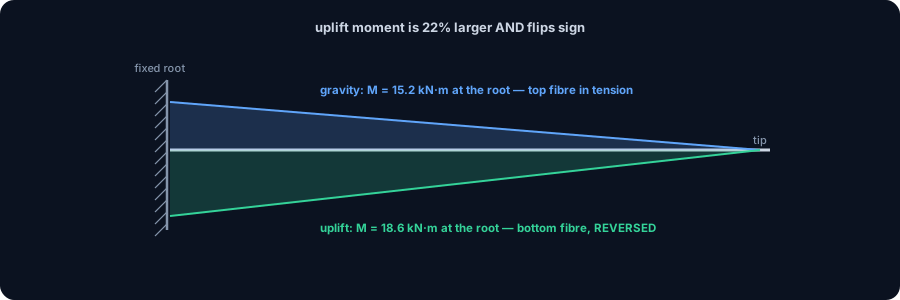
- On this worked 4 m cantilever the engine returns a gravity root moment of 15.2 kN·m and an uplift root moment of 18.6 kN·m. Uplift is 22 percent larger and it acts the other way, so the tension flips from the top fibre to the bottom and the support reaction reverses from a 7.6 kN downward bearing to a 9.3 kN upward pull.
- The bending check passes on a modest IPE 180 in both cases (utilisation 0.43 gravity, 0.53 uplift), so bending is not what sizes this canopy. The two checks that do are the ones gravity never shows you: tip deflection and the reversed connection.
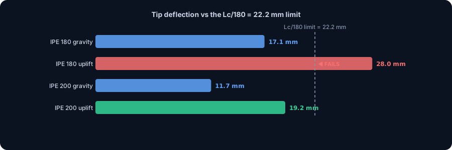
- Under service wind the tip deflects 28.0 mm, against 17.1 mm under service gravity, because the uplift load is bigger and a cantilever is deflection-hungry. Against a Lc/180 = 22.2 mm tip limit, gravity passes at L/234 and uplift fails at L/143, so serviceability is governed by uplift too. Going up to an IPE 200 brings the uplift tip back to 19.2 mm, L/208.
- The engine reproduces the closed form to the digit: wL squared over 2 for the root moment, wL for the root shear and reaction, and wL to the fourth over 8EI for the tip deflection. What you design to is equilibrium, not an estimate, and the equilibrium says: detail the connection and the holding-down for uplift, not for gravity bearing.
The wrong first question, and the right one
Ask "what canopy with a 4 m cantilever" and the reflex is to reach for gravity. It is a roof, it hangs 4 m off a line of columns, so pick a rafter stiff enough to carry the dead and roof loads over the overhang and check that it does not sag too far. For an enclosed floor beam that instinct is right, and our note on a mezzanine floor beam follows exactly that gravity-first path.
A canopy breaks the instinct, and it breaks it for a physical reason. A canopy is a free-standing roof, open underneath, so the wind reaches both of its faces at once. It pushes up on the soffit and it sucks up over the top, and the two add. On an exposed 4 m overhang that net uplift is usually larger than the gravity load the cantilever was carrying, and it points the other way. So the case that sizes this canopy is not the one you look up. It is wind uplift, and this article works one concrete canopy all the way through to show why, and what it changes. The short version: the same IPE section that looks finished under gravity is decided, at the end, by its tip deflection under wind and by a connection that gets pulled off instead of pressed down.
The worked canopy: a 4 m cantilever off a column line
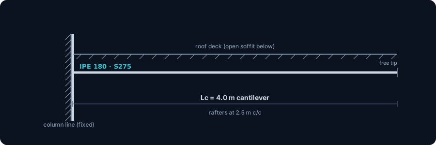
Here is the structure we carry through the piece. A single steel rafter cantilevering Lc = 4.0 m from a line of columns, rigidly connected at the column so the overhang has no prop at its far end, its tip hanging free. The rafters repeat along the frontage at 2.5 m on centre, so each one collects a 2.5 m wide strip of roof. A light metal deck sits on top, and — the defining feature — nothing closes the underside. This is a marquee over an entrance, a fuel-station forecourt roof, a loading-bay canopy: air flows freely beneath it.
The first-guess section is a hot-rolled IPE 180 in grade S275, a natural pick for a 4 m overhang carrying a light roof. Two facts about a cantilever decide everything downstream. First, its bending moment is not wL squared over 8 like a simple span, it is wL squared over 2, four times larger for the same load and length, and it is all piled at the one fixed end. Second, a cantilever is deflection-hungry: its tip moves as wL to the fourth over 8EI, roughly nine times the mid-span sag of a simply supported beam of the same span and load. A cantilever punishes both the moment at its root and the movement at its tip, and wind, as we will see, drives both.
Why a canopy's wind uplift beats its gravity
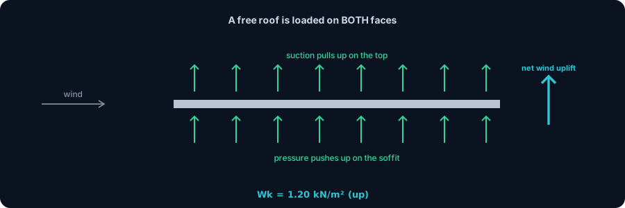
On an enclosed building the wind mostly presses and sucks on the outside skin, and the roof feels external suction partly offset by whatever internal pressure the building holds. A canopy has no inside. Both surfaces are external, so the wind acts on the top and the bottom of the same plane. Over most of a low canopy the flow lifts the roof from beneath while it accelerates and drops the pressure above, and the underside push and the topside suction combine into one net upward pressure. That is why the free-roof pressure coefficients in every wind code are large, and why they are given as a single net value across the thickness rather than as a top and a bottom read separately.
Put a number on it for this canopy. The net uplift works out to about 1.20 kN/m2 of upward pressure, which over the 2.5 m tributary strip is a line load of 3.00 kN/m acting up. Compare that with the gravity it carries: a dead load of roughly 0.30 kN/m2 (0.75 kN/m) and a roof imposed load of 0.25 kN/m2 (0.625 kN/m). The single upward wind load is larger than the dead and imposed loads put together, and it is the reason the answer to "what canopy" is written by the case that lifts, not the case that presses.
Two loads down, one bigger load up, and the sign that matters
Three load cases reach the rafter, and because they do not act together at full value we keep them apart and combine afterward. Over the 2.5 m spacing each area pressure becomes a line load:
- Dead load D, deck, fixings and self-weight, about 0.30 kN/m2, which is 0.75 kN/m down.
- Roof imposed load Lr, a maintenance allowance, about 0.25 kN/m2, which is 0.625 kN/m down.
- Wind W, the net uplift derived above, 3.00 kN/m up, the only load that lifts.
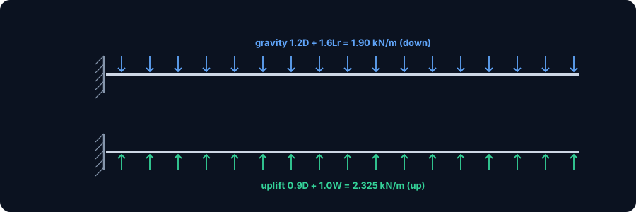
Two strength (LRFD) combinations bracket the design. The gravity maximum loads the dead and imposed loads together, 1.2D + 1.6Lr = 1.90 kN/m pressing down. The uplift combination does the opposite on purpose: it takes the dead load at its minimum factor, so nothing helps resist the lift, and pairs it with full wind, 0.9D + 1.0W, which nets to 2.325 kN/m acting up. Read those two numbers side by side. The uplift line load, 2.325 kN/m, is larger than the gravity one, 1.90 kN/m. Unlike a purlin, where uplift carries the smaller moment and wins only by unbracing the compression flange, here uplift wins on raw magnitude and it wins on sign. See our note on load combinations for why 0.9D pairs with the wind.
Gravity first, and a hand check that matches to the digit
Drop the cantilever into the CalcSteel engine, apply the gravity line load of 1.90 kN/m, and read the diagram. A cantilever under a uniform load gives the most compact answer in statics, and the engine returns it exactly:
- Peak bending moment at the fixed root, M = 15.2 kN·m, matching wL squared over 2 = 1.90 x 4.0 squared / 2 = 15.2 to four decimals. The moment is a triangle: zero at the free tip, maximum at the root.
- Shear and vertical reaction at the root, V = 7.6 kN, matching wL = 1.90 x 4.0 = 7.6, pressing down into the column.
- A fixing moment of 15.2 kN·m that the connection has to carry, with the top fibre of the rafter in tension because gravity sags the tip down.
This is the well-behaved case, the one a span table is built for. The top flange, held by the deck, is in compression; the moment sits at a value a small section swallows easily. If gravity were the whole story we would size for 15.2 kN·m, check the sag, and be done. It is not, and the next section is why.
Try it: put your own 4 m cantilever in
Before the uplift twist, get a feel for the cantilever demand yourself. The calculator below is the CalcSteel cantilever-beam calculator. Enter a length of 4 m and a uniform load of 1.90 kN/m, and it returns the fixed-end moment, the shear and the tip deflection, the same numbers the engine gave above. Then swap in the uplift value of 2.325 kN/m and watch the root moment climb to 18.6 kN·m and the tip movement grow with it. The sections that follow show why that bigger, reversed number is the one that decides the design.
Fixed-end moment
20 kN·m
M at the wall
Fixed-end shear
10 kN
V at the wall
Tip deflection δ
7.22 mm
= L/277
Tip rotation θ
0.0054 rad
0.310°
Utilization
65.0%
NBR 8800 · δ ≤ L/180
Geometry & support
Fixed at the wall (x = 0), free at the tip (x = L)
Section
Ix 1846 cm⁴ · Sx 185 cm³ · 22.4 kg/m
Point loads (↓ positive · x from the wall)
Distributed loads (uniform or trapezoidal)
None.
Model sketch
Diagrams — free PNG / SVG / CSV / PDF export, no watermark
Lightest catalog profiles that pass (974 flexural candidates · NBR 8800)
| Profile | Std | Weight | Total steel | σ util | δ util | |
|---|---|---|---|---|---|---|
| C 300x85x25x2 | BR | 8.1 kg/m | 16 kg | 97% | 88% | |
| U 300x90x2.25 | BR | 8.4 kg/m | 17 kg | 96% | 88% | |
| C 300x100x25x2 | BR | 8.5 kg/m | 17 kg | 88% | 80% | |
| U 300x100x2.25 | BR | 8.8 kg/m | 18 kg | 90% | 82% | |
| C 300x85x25x2.25 | BR | 9.1 kg/m | 18 kg | 87% | 79% |
Elastic bending (σ = M/Sx vs fy/γa1, γa1 = 1.10 — NBR 8800) + tip-deflection screening of the full flexural catalog (δ scales as 1/EI, so one FEM solve prices every section). Lateral-torsional buckling, shear and local buckling are NOT checked here — run the full NBR 8800 / AISC 360 verification in the 3D editor.
Wind uplift makes the moment bigger, and flips it
Now run the uplift combination, 2.325 kN/m acting up. The engine returns a root moment of 18.6 kN·m (wL squared over 2 = 2.325 x 16 / 2, matched exactly) and a root shear of 9.3 kN. Both are larger than the gravity values, and both point the other way. Three things change at once, and each one is a check gravity never raised:
- The moment grows. 18.6 kN·m against 15.2, a 22 percent jump, so the bending demand on the section comes from uplift, not gravity.
- The tension flips flanges. Under gravity the top fibre was in tension; under uplift the moment reverses and the bottom fibre goes into tension. The compression moves to the top flange the deck already braces, so this is not the purlin's lateral-torsional story, it is a straight sign reversal in the same section.
- The reaction reverses. Instead of a 7.6 kN force pressing down into the column, the support now feels a 9.3 kN pull upward, and the 15.2 kN·m fixing moment becomes an 18.6 kN·m moment the other way. The canopy is trying to peel itself off its supports.
That last point is the one a span table can never show, and it is where a canopy quietly gets dangerous. A connection sized to bear 7.6 kN downward and hold 15.2 kN·m one way is simply the wrong detail for a 9.3 kN uplift and 18.6 kN·m the other way.
Picking the section, and why gravity says yes
Now size the IPE 180. Its section properties, as the CalcSteel engine computes them, are the input to every check:
| Property | Value | Property | Value |
|---|---|---|---|
| Area A | 23.9 cm2 | Strong-axis modulus Sx | 142.7 cm3 |
| Inertia Ix | 1285 cm4 | Weak-axis inertia Iy | 100.7 cm4 |
Bending. Checked elastically, the design moment capacity is phi times Fy times Sx = 0.90 x 275 x 142.7 x 10 cubed = 35.3 kN·m. Against the gravity demand of 15.2 kN·m the utilisation is 0.43; against the larger uplift demand of 18.6 kN·m it is 0.53. Both pass, comfortably, and the compression flange is deck-braced in both cases so there is no lateral-torsional penalty. Read the bending column and the IPE 180 looks like the answer: uplift is the harder case, but the section carries it with room to spare.
So bending does not size this canopy. That is the quiet trap. On the purlin it was bending that failed, through buckling; here the bending is fine on a small section and the design is decided somewhere a moment check never looks. Two places, in fact, and both of them are worst under uplift.
The two checks gravity hides: the tip, and the connection
Tip deflection. A cantilever tip moves as wL to the fourth over 8EI, and because that grows with the load, the bigger service load wins. Under service gravity, D + Lr = 1.375 kN/m, the engine reports a tip movement of 17.1 mm, matching the closed form to four decimals. Under service wind, the net uplift of 2.25 kN/m (characteristic wind less the favourable dead), the tip moves 28.0 mm, 64 percent more, because the wind load is bigger. Against a common cantilever tip limit of Lc/180 = 22.2 mm, gravity passes at L/234 and uplift fails at L/143. Whatever deflection limit you adopt, it is the uplift movement that will breach it first.
| Section | Gravity tip (service) | Wind-uplift tip (service) |
|---|---|---|
| IPE 180 | 17.1 mm — L/234 | 28.0 mm — L/143, fails |
| IPE 200 | 11.7 mm — L/340 | 19.2 mm — L/208, passes |
The connection. The second hidden check is the support itself. Under gravity it bears 7.6 kN down and holds a 15.2 kN·m moment one way; under uplift it must resist a 9.3 kN pull upward and an 18.6 kN·m moment the other way. If the rafter lands on a column baseplate or a bracket, that reversal loads the holding-down bolts in tension and tries to overturn the support. A gravity-only detail — designed to bear down and to compress — has little or nothing in the bag for the uplift pull-off. On a canopy the anchorage is not an afterthought to the beam; under uplift it is often the governing element.
The answer: a section for uplift, and a connection for pull-off
Line the whole design up and the shape of the problem is clear. Bending is comfortable on the small section; the two governing checks are the uplift tip deflection and the uplift connection, and the IPE 180 that gravity passed fails the first of them.
| Check | Demand (governing case) | Capacity / limit | Result |
|---|---|---|---|
| Bending, IPE 180 | 18.6 kN·m (uplift) | 35.3 kN·m | 0.53, passes |
| Tip deflection, IPE 180 | 28.0 mm (uplift) | 22.2 mm (Lc/180) | L/143, fails |
| Tip deflection, IPE 200 | 19.2 mm (uplift) | 22.2 mm (Lc/180) | L/208, passes |
| Connection uplift | 9.3 kN up + 18.6 kN·m reversed | detail-dependent | design for uplift |
So the answer to "what canopy for a 4 m cantilever" is not a name off a table. It is an IPE 200 in S275 — the step up that brings the wind-uplift tip deflection back inside Lc/180 while bending stays under half capacity — carried on a connection and holding-down detailed for the 9.3 kN uplift pull and the reversed 18.6 kN·m moment. Both of those requirements were invisible in the gravity case. Going up a section here buys deflection, not bending strength, and the anchorage is a separate design in its own right. That is the whole difference between an ordinary roof beam and a canopy: the section is set by the movement under wind, and the detail is set by the pull under wind.
What the codes ask, on three continents
The workflow, gravity demand then a larger reversed uplift demand then two checks the moment never showed, is the same everywhere. The packaging differs, and the wind side in particular has a dedicated home in each code because a free roof is its own load case.
- United States (ASCE 7-16). Open buildings and monoslope free roofs are covered by their own net pressure coefficients (Chapter 27 for the main system, with the monoslope-free-roof figures, and Chapter 30 for components and cladding). The strength combination 0.9D + 1.0W is the uplift case, and ASCE 7 is explicit that the load path to the foundation, the holding-down included, must be designed for that net uplift.
- Europe (EN 1991-1-4). Section 7.3 gives canopy roofs their own net pressure coefficients cp,net and overall force coefficients, with large uplift values because both faces are exposed. The permanent-action-favourable combination of EN 1990 pairs 0.9G (or the equivalent partial factor) with the leading wind, and the member is then verified to EN 1993.
- Brazil (NBR 6123 with NBR 8800). NBR 6123 treats isolated roofs and marquises explicitly, again with net coefficients that capture the two-sided loading, and the member and its connections are designed to NBR 8800 for the resulting reversal.
Different symbols, one idea. Every one of these codes gives the canopy a large net uplift and a combination that removes the helpful dead load, and every one asks you to carry that uplift all the way into the ground. The CalcSteel engine checks the member against AISC 360, Eurocode 3 and NBR 8800 from the same forces, so the governing case is computed rather than remembered. For where the wind pressure comes from, our note on wind loads covers the pressure side.
Common mistakes and FAQ
"It is a roof, so gravity sizes it." Not a canopy. A canopy is open underneath, so wind loads both faces and the net uplift is larger than the gravity it carries. On this cantilever the uplift moment (18.6 kN·m) beats the gravity one (15.2 kN·m) and reverses it. Gravity is the case you can do in your head; it is not the case that governs.
"The bending passes, so the section is fine." Bending passes on an IPE 180 in both cases. The section is not fine, because the wind-uplift tip deflection (28.0 mm) fails the Lc/180 limit the gravity deflection (17.1 mm) passed. On a canopy the section is usually set by deflection under wind, not by moment.
"I designed the connection for the gravity reaction." The gravity reaction presses 7.6 kN down. The uplift reaction pulls 9.3 kN up and reverses the fixing moment to 18.6 kN·m. A bearing detail is the wrong detail; the holding-down bolts and the bracket have to be designed in tension for the pull-off, which is a different calculation entirely.
"Wind uplift is a components-and-cladding thing, the frame feels less." The local peak coefficients used for cladding and fixings are indeed higher, but the area-averaged net uplift that reaches the rafter is still large for a free roof, and it is still bigger than the gravity it offsets. The frame does not get a pass because the fixings see more.
"Just go up two sizes and forget the wind." Going up a size fixes the deflection, but no beam size fixes an anchorage that has no tension capacity. You still have to detail the connection for the uplift pull, whatever section carries the span.
From a cantilever length to the deciding case
So, what canopy with a 4 m cantilever? Not a section read off a gravity table. On this roof an IPE 200 in S275 is the right answer, but only once you have run the case the table cannot: wind uplift, which on a free-standing roof is larger than the gravity it carries, reverses the moment at the support, and drives both the tip deflection that sizes the section and the pull that sizes the connection. The section is an output of the governing check, and for a canopy that check lifts, it does not press.
The demand side is not guesswork, it is equilibrium: on this cantilever the engine reproduced wL squared over 2, wL and wL to the fourth over 8EI to four decimals, for both the gravity and the uplift cases. The judgement lives in two places a moment check never looks, the tip and the anchorage, and both are worst under wind. CalcSteel runs the load cases, forms the combinations and reports the governing bending, shear and deflection for the section at once, and it reports the reversed reaction the connection has to hold. Model your own 4 m canopy in the editor, add the 0.9D + 1.0W uplift combination, and watch the tip deflection and the reaction change sign. For the neighbouring problems, our worked purlin under uplift and our guide to deflection and serviceability cover the buckling mode and the movement limits this canopy lives between.
Sources
- 1.ASCE 7-16, Minimum Design Loads and Associated Criteria for Buildings and Other Structures (open buildings and monoslope free roofs, Chapters 27 and 30; load combination 0.9D + 1.0W)
- 2.EN 1991-1-4, Eurocode 1: Actions on structures, Part 1-4: Wind actions (Section 7.3, canopy roofs, net pressure coefficients cp,net)
- 3.EN 1990, Eurocode: Basis of structural design (permanent action favourable combination; serviceability deflection limits, Annex A1.4)
- 4.ABNT NBR 6123, Forcas devidas ao vento em edificacoes (isolated roofs and marquises), with NBR 8800 for member and connection design
- 5.AISC 360, Specification for Structural Steel Buildings (member resistance in bending, shear and serviceability)
Try CalcSteel for free
Model, analyze and design steel structures in your browser. No install, no signup.
Open the 3D editor