Virtual Work Method: Computing a Deflection Without a Single Differential Equation
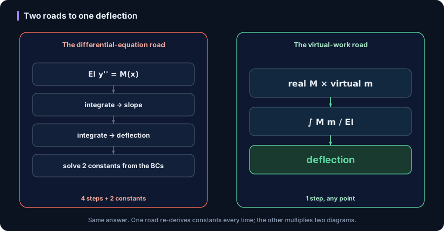
The textbook route to a beam deflection is to integrate the elastic-curve differential equation EI y'' = M(x) twice, carry two constants, and pin them with boundary conditions. Ask for a rotation instead, or a different point, and you redo the whole evaluation. For a frame or a truss there is not even a tidy y(x) to integrate. The virtual work method, the unit-load method, replaces all of that with one scalar you can read off two diagrams: apply an imaginary unit load where you want the displacement, multiply its force diagram by the real one, divide by the stiffness. Here it is worked twice against the shipping CalcSteel FEM engine, on a real IPE 360 beam (two different deflections from one analysis) and a real steel truss (a deflection with no calculus at all), each matching the solver to the third decimal.
Key takeaways
- Virtual work (the unit-load method) gives one deflection at one point and direction directly, with no differential equation and no boundary constants: delta = integral of (M m / EI) ds for bending, and the sum of (n N L / EA) over members for a truss.
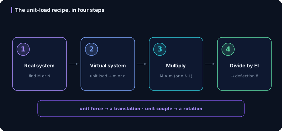
- The recipe is four steps: solve the real structure for its force diagram (M or N), remove the real loads and apply a single unit dummy load at the exact point and direction you want, get the virtual diagram (m or n), then multiply the two diagrams and divide by EI (or EA).
- Diagram multiplication (Vereshchagin's rule) turns the integral into arithmetic: area of one diagram times the ordinate of the other, straight, diagram at that area's centroid. No integration sign in sight.
- Worked on a real IPE 360 simply supported beam (L = 6 m, w = 15 kN/m) in the FEM engine: midspan deflection 8.05 mm (= 5wL^4/384EI) and left-support rotation 0.00429 rad (= wL^3/24EI), both from the SAME real moment diagram, each matching the solver to the decimal.
- Same method, zero calculus for a truss: a king-post truss (span 6 m, RHS 90x90x5, 40 kN hung at the bottom mid-joint) gives a loaded-joint deflection of 1.03 mm as a five-row sum of nNL/EA, matching the FEM node displacement.
The differential-equation tax on a deflection
Every mechanics course teaches the deflection of a beam the same way: start from the elastic-curve equation EI y'' = M(x), integrate once for the slope, integrate again for the deflection, and you are left with two integration constants that only the boundary conditions can fix. It works. It is also a tax you pay again every time the question changes. Want the slope instead of the deflection? Re-evaluate. Want it at the quarter point rather than midspan? Re-evaluate. Move to a portal frame, where the elastic curve bends around a rigid corner, and there is no single tidy y(x) to integrate at all. Move to a truss and the differential equation was never the right tool in the first place.
The virtual work method, also called the unit-load method, throws the differential equation out and replaces it with one number you assemble from two force diagrams. The idea in a sentence: to find the displacement at a point, apply an imaginary unit load there, and set the external work that unit load would do through the real displacement equal to the internal work of its forces through the real deformations. Rearranged, that equality is the displacement. No second integration, no constants, no boundary conditions to chase. This article works it end to end, twice, with the shipping CalcSteel FEM engine as the referee: a real steel beam where one analysis yields two different answers, and a real steel truss where the whole calculation is a five-row table.
The principle: work in equals work out, with an imaginary load
The principle of virtual work says that for a body in equilibrium, the external work done by a force system moving through any compatible set of displacements equals the internal work done by its stresses through the matching deformations. The unit-load method is one clever use of it. Build a virtual (dummy) system: the same structure, all real loads removed, carrying a single unit load placed exactly at the point and in exactly the direction of the displacement you want (a unit force for a translation, a unit couple for a rotation). Let that unit load be the external force system, and let the real deformations be the displacements it rides through.
External virtual work is then simply 1 × delta, the unit load times the unknown displacement. Internal virtual work is the sum, over the whole structure, of each virtual internal force acting through the real deformation it causes. For a member in bending the real curvature is M/EI, so the internal work density is m × (M/EI); for an axially loaded bar the real elongation is NL/EA, so it is n × (NL/EA). Setting external equal to internal gives the master equation, one line that covers beams, frames, and trusses:
1 · delta = integral of (M m / EI) ds + integral of (N n / EA) ds + integral of (V v / GA) ds + integral of (T t / GJ) ds
Here capitals (M, N, V, T) are the real internal forces and lowercase (m, n, v, t) are the virtual ones from the unit load. You keep only the terms the structure actually has: a slender beam is almost pure bending, a truss is pure axial, a shaft is pure torsion. Everything that follows is just this equation, evaluated.
The four-step recipe
Stripped to a procedure, computing any single deflection or rotation is four moves:
- Real system. Apply the actual loads and find the real internal force diagram: M(x) for a beam or frame, the axial force N in each truss member. This is the one analysis you were going to do anyway; here the FEM engine produces it.
- Virtual system. Remove every real load. Apply a single unit load at the exact location and direction of the displacement you want: a unit force for a translation, a unit couple for a rotation. Find its internal diagram m(x) or n. Because it carries just one unit load, this diagram is always simple: piecewise straight lines for a beam, a quick joint solve for a truss.
- Multiply. Integrate the product M · m along every member (beams and frames), or sum n · N · L over the members (trusses).
- Divide by stiffness. Divide the bending term by EI and the axial term by EA. The result is the displacement. Its sign tells you whether the movement is with the unit load (positive) or against it (negative).
The reason this beats double integration in practice is step 1 happens once. Every new question, a different point, a rotation, the relative movement of two joints, only swaps the cheap virtual system in step 2. We will do exactly that below: one real beam analysis, two different displacements.
The worked beam: one real analysis
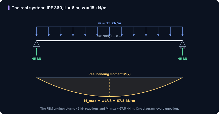
Take a simply supported IPE 360, span L = 6.0 m, carrying a uniform load w = 15 kN/m (a typical floor-beam line load), in grade MR250 steel. The reactions are wL/2 = 45 kN at each end. The real bending moment is a parabola, zero at the supports and peaking at midspan:
M(x) = 45x − 7.5x^2 (kN·m, x in m), with M_max = wL^2/8 = 67.5 kN·m.
We built this beam in the shipping CalcSteel FEM engine (the span meshed into eight elements). It returns the reactions and M_max = 67.500 kN·m to the decimal. It also reports the section it actually used: the engine recomputes section properties from the geometry and returns A = 72.7 cm^2 (matching the catalogue) and a second moment of area I = 15 728 cm^4, about 3 percent under the 16 270 cm^4 table value because the sloped flanges and root fillets sit outside the closed formula. We use the engine's own I throughout, so the hand integral and the FEM deflection are the same number. With E = 200 GPa, that is EI = 31 456 kN·m^2. Now we ask the beam two different questions, and answer both from this one diagram.
Deflection at midspan: multiply two diagrams
First question: the vertical deflection at midspan. Build the virtual system: remove w, and hang a single unit downward force (1) at midspan. Its moment diagram m(x) is a triangle, zero at both supports and peaking at L/4 = 1.5 kN·m at the center. The deflection is the master equation with only the bending term:
delta = (1/EI) · integral of M(x) m(x) dx
Multiplying the real parabola by the virtual triangle over the span gives integral of M m dx = 253.125 kN·m^3, a pure geometric product that does not know the section. Divide by EI:
delta = 253.125 / 31 456 = 0.008047 m = 8.05 mm.
That is exactly the classic 5wL^4/384EI, and the FEM engine's midspan node reports 8.047 mm, the same to the decimal. No integration constants, no boundary conditions. And notice what did the work: a triangle times a parabola, one integral, one division.
Rotation at the support: same diagram, new unit load
Second question, and this is where the method earns its keep: the slope (rotation) at the left support. The real system does not change, so M(x) is the same parabola. Only the virtual system changes: remove w and apply a unit couple (1 kN·m) at the left support. Its moment diagram m-bar(x) is a straight line from 1 at the left support down to 0 at the right.
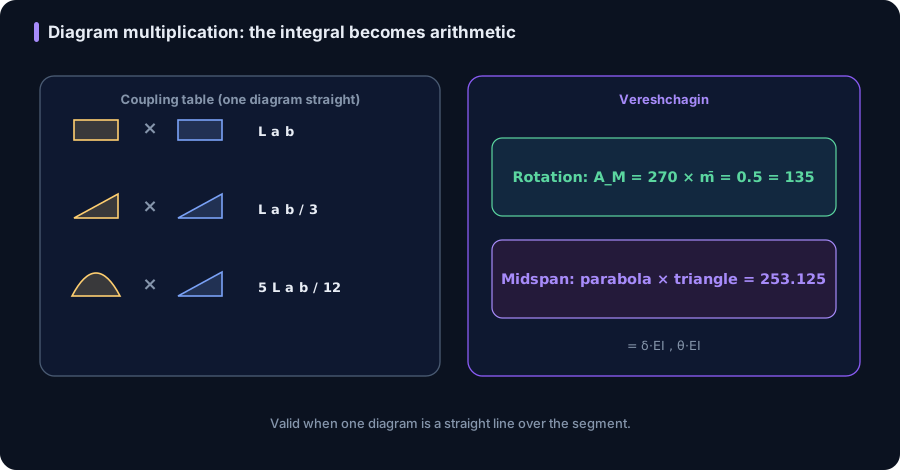
Because m-bar is a single straight line over the whole span, the multiplication is one step of Vereshchagin's rule: take the area of the real parabola and multiply by the ordinate of the straight virtual diagram at that area's centroid. The parabola's area is (2/3) × L × M_max = (2/3) × 6 × 67.5 = 270 kN·m^2, its centroid is at midspan, and m-bar there is 0.5. So integral of M m-bar dx = 270 × 0.5 = 135 kN·m^2, and:
theta = 135 / 31 456 = 0.004292 rad = 0.246 degrees.
That is exactly wL^3/24EI, and the FEM node rotation is 0.00429 rad. One real analysis has now produced two independent answers, a deflection and a rotation, each for the cost of a one-line virtual diagram. Ask for the quarter-point deflection and it is the same move a third time (the engine puts it at 5.73 mm). This reuse is the whole reason the method exists.
Diagram multiplication: the integral becomes arithmetic
The step that feels like magic, replacing an integral with a single product, is Vereshchagin's rule, and it is exact whenever at least one of the two diagrams is a straight line over the segment. Over such a segment:
integral of M m dx = (area of one diagram) × (ordinate of the straight diagram at the first one's centroid).
A short table of the common pairs, rectangle by rectangle, triangle by triangle, parabola by triangle, and so on, turns every beam and frame deflection into areas and centroid ordinates you can read off a sketch. Structural analysis uses these coupling tables exactly so nobody integrates a product of diagrams by hand.
Two cautions keep it honest. First, the shortcut needs one diagram straight; a parabola times a parabola has to be integrated or split. Second, a kink counts. The midspan virtual triangle above bends at the center, so strictly you split the span at the kink and add two products (each a straight segment times the parabola); it still comes to 253.125, still just arithmetic. The support-rotation virtual diagram had no kink, so it was a single 270 × 0.5.
The worked truss: a deflection with no calculus at all
A truss member carries only axial force, constant along its length, so the bending integral collapses to a sum with one row per member. There is no differential equation anywhere in a truss to begin with:
delta = sum of (n N L / EA)
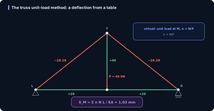
Take a king-post truss: a bottom chord through L(0,0), M(3,0), R(6,0) in metres, with an apex at T(3,3); members are the bottom chords LM and MR, the diagonals LT and TR, and the vertical TM. It is pinned at L, on a roller at R, and a load P = 40 kN hangs at the bottom mid-joint M. Every member is an RHS 90x90x5 (A = 17.0 cm^2), grade MR250.
Real forces come from the method of joints, and the FEM engine returns them to the decimal: chords LM = MR = +20 kN (tension), diagonals LT = TR = −28.28 kN (compression, −P/√2), vertical TM = +40 kN (tension). We want the vertical deflection at M, so the virtual system is a unit downward load at M. Because the geometry and supports are unchanged, its member forces are simply n = N/P. The whole calculation is one table:
| Member | N (kN) | n | L (m) | nNL (kN·m) |
|---|---|---|---|---|
| LM | +20 | +0.5 | 3.000 | 30.0 |
| MR | +20 | +0.5 | 3.000 | 30.0 |
| LT | −28.28 | −0.707 | 4.243 | 84.9 |
| TR | −28.28 | −0.707 | 4.243 | 84.9 |
| TM | +40 | +1.000 | 3.000 | 120.0 |
| Sum | 349.7 | |||
Then divide by the axial stiffness EA = 17.0 cm^2 × 20 000 kN/cm^2 = 340 000 kN:
delta = 349.7 / 340 000 = 0.00103 m = 1.03 mm.
The FEM node M drops 1.029 mm. A real steel deflection from five rows of arithmetic, with the differential equation nowhere in sight.
Where it goes next: frames, indeterminacy, reciprocity
The same master equation scales in three directions worth knowing.
Frames and every action at once. A frame simply carries more of the terms: delta = integral of (Mm/EI) + integral of (Nn/EA) + integral of (V v/GA) + integral of (Tt/GJ). You add the terms the structure has and drop the rest. We dropped shear and axial from the beam and still matched the FEM to the decimal, because for a slender beam they are genuinely negligible; a truss keeps only the axial term; a shaft keeps only torsion. The bookkeeping never changes: real diagram times virtual diagram over stiffness.
Statically indeterminate structures. Virtual work is the engine of the classical force (flexibility) method. You release the structure to a determinate one, treat each redundant as an unknown unit load, use the unit-load integral to compute the displacements that the redundants must cancel, and solve a small compatibility system for them. It is the same integral, now enforcing compatibility instead of reporting a deflection. See our companions on where the hand method stops and the continuous-beam worked check.
Reciprocity for free. Because M m and m M are the same product, Maxwell-Betti reciprocity falls straight out: the deflection at A due to a unit load at B equals the deflection at B due to a unit load at A. That is not just elegant, it is a free audit on any influence coefficient you compute.
Try it: the same beam, live
The calculator below is the same simply supported beam. Set the span to 6 m and a uniform load of 15 kN/m, pick an IPE 360, and read the maximum deflection: it is the 8.05 mm you just assembled by multiplying a parabola and a triangle, now shown next to the code deflection limit (L/250, L/360, and so on) so you see the serviceability check in the same place. Change the section or the load and the deflection tracks live, which is the fastest way to feel how delta scales with L^4 and 1/I.
It computes the beam's maximum deflection directly from the closed form, so use it as the instant sanity check on any virtual-work integral you do by hand: if your product-of-diagrams answer and this number disagree, one of the two has a mistake. It is free and needs no login for the calculation.
Max moment
45 kN·m
Max shear
30 kN
Max deflection
10.55 mm
= L/569
Bending stress σ
84.4 MPa
σ = M/Sx
Utilization
44.0%
NBR 8800 · δ ≤ L/250
Geometry & supports
Section
Ix 7999 cm⁴ · Sx 533 cm³ · 42.2 kg/m
Point loads (↓ positive)
None — add as many as you need.
Distributed loads (uniform or trapezoidal)
Model sketch
Diagrams — free PNG / SVG / CSV export, no watermark
Step-by-step — the calculation memory of YOUR beam
IPE 300 · L = 6 m · fy = 250 MPa
1. Reactions (equilibrium of the solved FEM model)
ΣFy = 0 · ΣM = 0
R_A = 30 kN · R_B = 30 kN
2. Peak shear (read from the SFD)
Vmax = |V(x)|max
Vmax = -30 kN @ x = 6 m
3. Peak moment (read from the BMD)
Mmax = |M(x)|max
Mmax = 45 kN·m @ x = 3 m
4. Peak deflection
EI = 15998 kN·m² (E = 200 GPa)
δmax = 10.55 mm @ x = 3 m = L/569
5. Elastic bending stress
σ = Mmax / Sx = 45.00 × 10³ / 533.3
σ = 84.4 MPa
6. Bending check — both codes, side by side
NBR 8800: σ ≤ fy/1.10 = 227.3 MPa · AISC 360: σ ≤ 0.90·fy = 225 MPa
NBR 37.1% PASS · AISC 37.5% PASS
7. Deflection check (serviceability — code-independent)
δ ≤ L/250 = 24 mm
10.55 mm / 24 mm = 44.0% PASS
Recomputed live from the current inputs by the direct-stiffness FEM engine — change any load and every step updates. Reproduce it by hand with the formulas in the sections below.
Lightest catalog profiles that pass (974 flexural candidates · NBR 8800)
| Profile | Std | Weight | Total steel | σ util | δ util | |
|---|---|---|---|---|---|---|
| W310x21 | AISC | 21 kg/m | 126 kg | 83% | 98% | |
| VS 300x23 | BR | 22.6 kg/m | 136 kg | 71% | 84% | |
| U 300x90x6.3 | BR | 23.1 kg/m | 139 kg | 82% | 98% | |
| U 300x100x6.3 | BR | 24.1 kg/m | 145 kg | 77% | 91% | |
| VS 250x25 | BR | 24.6 kg/m | 148 kg | 70% | 100% |
Elastic bending (σ = M/Sx vs fy/γa1, γa1 = 1.10 — NBR 8800) + deflection screening of the full flexural catalog. Lateral-torsional buckling, shear and local buckling are NOT checked here — run the full NBR 8800 / AISC 360 verification in the 3D editor.
How to check a virtual-work result you did not hand-derive
You will let a solver or a calculator produce most deflections. The skill worth keeping is auditing them, and virtual work gives you fast, cheap checks.
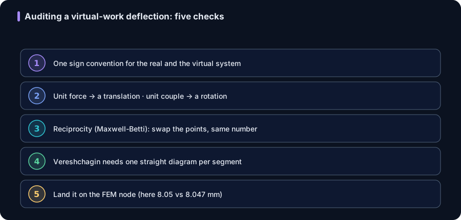
1. One sign convention, both systems. Use the same sign rule for M and m (and for N and n). A positive answer means the real displacement is in the direction of the unit load; negative means opposite. Mixing conventions between the real and virtual systems is the most common silent error.
2. Unit load matches the unknown. A translation needs a unit force and comes out in length; a rotation needs a unit couple and comes out in radians. If a rotation query used a unit force, the dimensions will not close.
3. Reciprocity is a free retest. Swap the load point and the measurement point; Maxwell-Betti says you must get the same number. It costs one extra virtual system and catches transcription errors.
4. Vereshchagin needs one straight diagram. If both diagrams curve over a segment, the area-times-centroid shortcut is invalid there: split at kinks or integrate that piece. A parabola times a parabola is the classic trap.
5. Land it on the FEM node. The solver reports the nodal displacement directly. Your hand integral should hit it; here both worked checks matched to the third decimal (8.05 vs 8.047 mm, 1.03 vs 1.029 mm). A gap larger than rounding means a term is missing or a diagram is wrong.
Common mistakes and FAQ
Leaving the real load on the virtual system. The virtual system carries ONLY the unit dummy load. If the actual w or P is still on it while you read m, the virtual diagram is wrong and so is every product built from it.
Using a force when you want a rotation. A unit force gives a translation; a unit couple gives a rotation. They are duals, and picking the wrong one gives an answer with the wrong dimensions.
Multiplying two curved diagrams with the shortcut. Vereshchagin's rule needs one diagram straight over the segment. A parabola against a parabola must be integrated or split; applying area-times-centroid blindly there is simply wrong.
Dropping the axial and shear terms when they matter. For slender beams and frames, bending dominates and the single integral of Mm/EI is enough (it matched the FEM to the decimal here). For short deep members, or when you specifically want axial shortening, keep the integral of Nn/EA and the shear term.
Does it work for statically indeterminate structures? Yes, as the engine of the force method: the same unit-load integral, used to enforce compatibility on the redundants.
Does the section have to be prismatic? No. EI can vary along the member; the integral just carries I(x), or you sum segment by segment with each segment's stiffness.
Why does a matrix FEM match this classical hand method so exactly? Because the displacement-method finite element solution for a prismatic Euler-Bernoulli beam is nodally exact under distributed load, and virtual work is the very energy statement the finite element method is built on. They are two views of one principle, which is why they agree to the decimal.
Key takeaways
- Virtual work (the unit-load method) computes one deflection or rotation directly, with no differential equation and no integration constants: 1 · delta = integral of Mm/EI ds for bending, sum of nNL/EA for trusses.
- The recipe is four steps: real diagram (M or N), a single unit load at the target for the virtual diagram (m or n), multiply the two, divide by EI or EA. A unit force gives a translation; a unit couple gives a rotation.
- Vereshchagin's rule makes the multiplication arithmetic: area of one diagram times the straight diagram's ordinate at that area's centroid. No integration sign, provided one diagram is straight over the segment.
- Worked on an IPE 360 beam (L = 6 m, w = 15 kN/m) in the FEM engine: midspan deflection 8.05 mm and support rotation 0.00429 rad, both from one real analysis, each matching the solver to the decimal.
- Worked on a king-post truss (RHS 90x90x5, 40 kN): the loaded-joint deflection is 1.03 mm from a five-row sum of nNL/EA, again matching the FEM node. The same principle drives the force method and hands you Maxwell-Betti reciprocity for free.
Sources
- 1.Hibbeler, Structural Analysis (virtual work, unit-load method, Vereshchagin's rule)
- 2.Gere and Goodno, Mechanics of Materials (strain energy, deflections, Castigliano's theorem)
- 3.Ghali, Neville and Brown, Structural Analysis: A Unified Classical and Matrix Approach (virtual work and the flexibility method)
- 4.Timoshenko and Young, Theory of Structures (classical energy methods)
- 5.Eurocode EN 1993-1-1, Design of steel structures: General rules (serviceability deflection limits)
Try CalcSteel for free
Model, analyze and design steel structures in your browser. No install, no signup.
Open the 3D editor