Steel Stair Stringer: Sized for the Load the Code Actually Asks
A steel stair stringer is an inclined beam, and it goes wrong in two quiet ways: it gets loaded like an ordinary floor when the code asks for far more, and it gets analysed as a flat beam when it is really a tilted one. This is the walkthrough that fixes both. We pin down the uniform-plus-concentrated load the code actually requires (ASCE 7, Eurocode and NBR side by side), show why the bending moment follows the horizontal run while the deflection follows the true inclined length, and size a real public-stair channel end to end on the CalcSteel FEM engine, where the strength check passes a UPN 120 but the deflection check is what really chooses the section.
Key takeaways
- A stair carries more than the floor it connects: codes ask for a uniform load (ASCE 7 uses 4.79 kN/m2, Eurocode category A 2 to 4 kN/m2 and category C up to 5, NBR 6120 uses 3.0 kN/m2 for public access) plus a separate concentrated load, and you design for whichever governs.
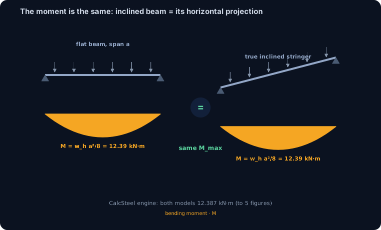
- The bending moment of an inclined stringer equals that of a flat beam spanning the horizontal run: M_max = w_h a^2 / 8 with the plan (horizontal) load and the horizontal going a. Using the longer inclined length for moment only over-designs it.
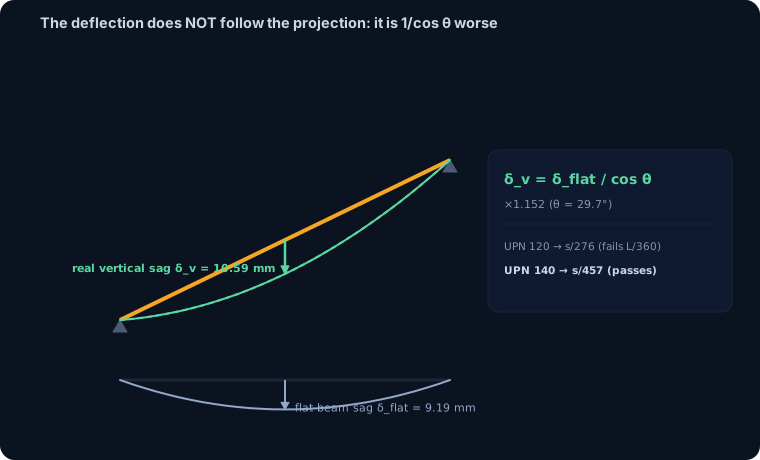
- Deflection does not follow the horizontal projection. The real inclined member sags 1/cos(theta) more than its flat shadow (about 15% at 30 degrees), so serviceability must be checked on the true inclined length s, not on a.
- Worked public stair (run a = 4.20 m, rise 2.40 m, live 4.0 kN/m2): the engine returns M_Ed = 12.39 kN.m and V_Ed = 11.80 kN. A UPN 120 passes strength at 85%, but its imposed deflection is s/276; the L/360 limit pushes the section up to a UPN 140 (60% strength, s/457). Deflection governs.
- The code concentrated load here gives M = P a / 4 = 3.15 kN.m, well below the uniform case, so it is really a local tread check; the incline also adds a small axial force (5.85 kN, raising utilization by about two points), code-required but rarely decisive.
An inclined beam that gets loaded and analysed wrong
Of all the steel members a building hides, the stair stringer is the one most often sized on a shrug. It looks minor: a channel running under the treads, a member you could pick from a table by eye. Yet it fails design review for two specific reasons, over and over, and both come from treating it as something simpler than it is.
The first is the load. A stair is not a floor. Every major code deliberately asks a stair to carry more than the room it serves, because a stair is where a crowd bunches up, and where a single person lands their whole weight on one step. Size the stringer for the 2 kN/m2 you used on the floor slab and you have under-loaded it before you started.
The second is the geometry. A stringer is not a flat beam; it is tilted, typically around 30 degrees. That tilt changes which span you use, and here is the trap that catches even careful engineers: the bending moment and the deflection do not use the same length. The moment follows the horizontal run; the deflection follows the true inclined member. Get those two mixed up and you either waste steel or, worse, hand over a stair that bounces.
This guide fixes both. We take one real public stair, read the load the code actually asks for, and size the channel from moment to deflection to the concentrated check, with every number produced by the CalcSteel finite-element engine and checked against closed-form theory to three decimals. The free CalcSteel beam calculator runs the same math in your browser, and it is the tool embedded halfway down so you can size your own stringer as you read.
What a stair stringer is, and how it is modelled
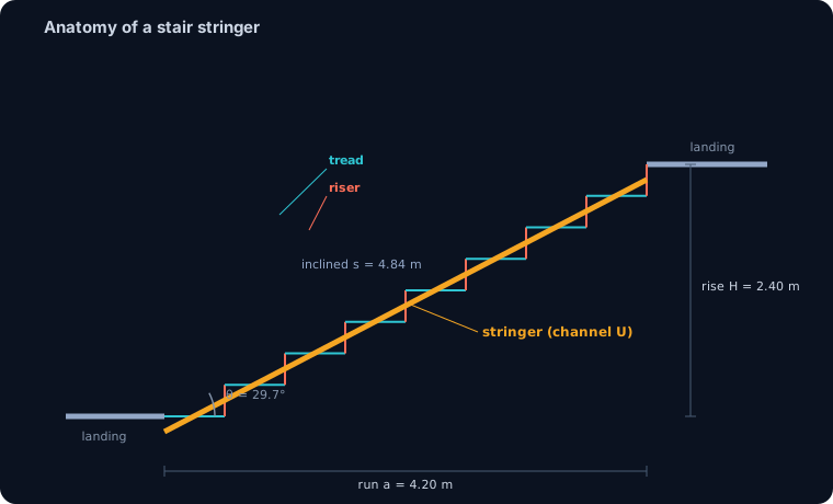
A stair stringer is the inclined beam that runs along the flight and carries the treads down to the supports at each end. In steel it is usually a channel (a hot-rolled U or a cold-formed C), sometimes a flat plate or a folded plate, and a typical flight runs on two of them, one under each side of the treads.
The treads span across between the two stringers and deliver their load to them as a line of small reactions; smeared along the stringer, that is a uniform load per metre. Each stringer therefore behaves as a beam carrying roughly half the stair, and the standard, safe idealisation is a simply supported beam: pinned at the bottom landing, on a roller at the top (or the reverse), free to rotate at both ends. That is conservative for strength, because a real stringer usually has some end continuity or a bolted connection that helps, and it is the model every hand method and every calculator in this article uses.
Two real-world details make the idealisation honest. First, the treads, welded or bolted across the top flange at close spacing, brace the stringer against lateral-torsional buckling, so for a channel under gravity you can usually take the full bending capacity without a slenderness penalty. Second, the member is inclined, which means the vertical load it carries has a component along its own axis: a small axial force rides alongside the bending. We will size the bending first, because it dominates, then come back and show the axial is a two-percent effect.
The load the code actually asks for
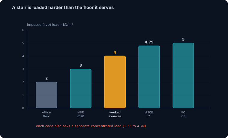
Here is the part that gets skipped. Open any modern loading code to its imposed-load table and stairs get their own line, and that line is higher than the floor it connects to. The reason is physical: stairs concentrate people during normal use and especially during egress, and they take a punishing single-step load.
Every code pairs two demands, and you check both:
- A uniform load over the plan area, for the crowd case.
- A concentrated load on a small area, for the single heavy step, wheel or point.
You then design for whichever produces the larger effect. The three codes an engineer is most likely to meet line up like this:
| Code | Uniform (plan) | Concentrated |
|---|---|---|
| ASCE 7-22 / IBC (stairs and exits, other than one and two-family dwellings) | 4.79 kN/m2 (100 psf) | 1.33 kN (300 lb) on a small area |
| Eurocode EN 1991-1-1 (category A stairs) | 2.0 to 4.0 kN/m2 | 2.0 to 4.0 kN |
| Eurocode EN 1991-1-1 (category C, assembly and escape) | up to 5.0 kN/m2 | 4.0 to 7.0 kN |
| ABNT NBR 6120:2019 (stairs with public access) | 3.0 kN/m2 | 2.5 kN |
Notice the spread. A residential floor sits near 1.5 to 2.0 kN/m2; the same building's egress stair can be asked for 4 to 5 kN/m2, more than double. That single fact is the one this article's title points at, and the most common sizing error in the whole subject: the stringer inherits the floor load, not the stair load. For the worked example we design a public-access stair to a uniform live load of 4.0 kN/m2, a value that sits inside the Eurocode and NBR public bands and just under the ASCE figure, and we carry the concentrated case alongside it.
From plan load to line load: the stair geometry
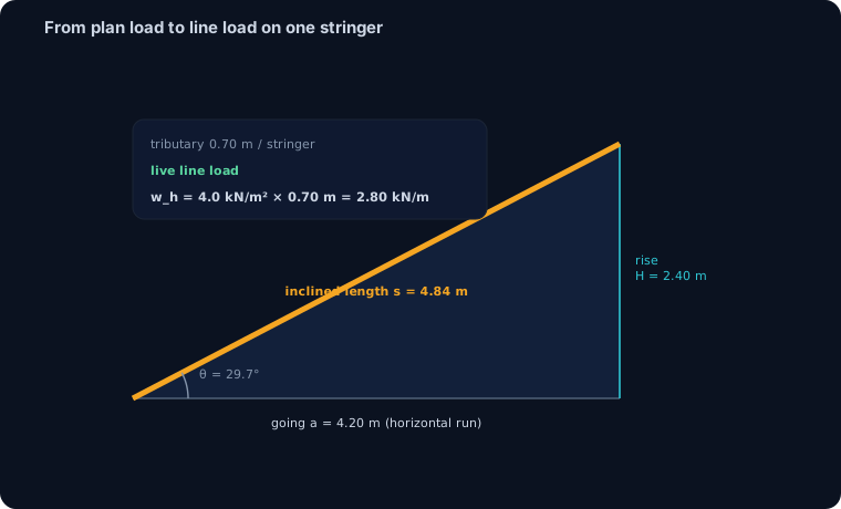
Now turn that pressure into a load per metre on one stringer, which needs the stair's geometry. Our worked flight is a straight public stair:
- Going (horizontal run) a = 4.20 m, the distance the stair covers on plan.
- Rise H = 2.40 m, the height it climbs.
- So the angle is theta = arctan(2.40 / 4.20) = 29.7 degrees, and cos(theta) = 0.868, a normal, comfortable public slope.
- The inclined length of the member is s = sqrt(a^2 + H^2) = 4.84 m. This is the real length of steel you order, and it is longer than the going.
- The flight is 1.40 m wide on two stringers, so each takes a tributary width of 0.70 m.
Codes give load per unit plan area, because that is how people and furniture are counted, so the tributary is measured horizontally. One stringer's uniform line load, referred to the horizontal run, is the pressure times the tributary width:
- Live: wh,live = 4.0 kN/m2 x 0.70 m = 2.80 kN/m.
- Dead (steel treads, two channels, a light finish and a rail allowance, about 1.5 kN/m2): wh,dead = 1.5 x 0.70 = 1.05 kN/m.
- Factored for strength (EN 1990: 1.35 dead + 1.5 live): wh = 1.35 x 1.05 + 1.5 x 2.80 = 5.62 kN/m. (An ASCE LRFD 1.2D + 1.6L combination lands within a few percent of the same figure.)
The subscript h is doing real work here. This is the load per metre of horizontal run, and in the next section it is exactly the intensity the moment formula wants. Keep it separate in your head from a load per metre of inclined steel; the two differ by cos(theta), and confusing them is the second classic error.
The moment follows the horizontal run
Here is the result that makes stair stringers easy once you know it, and a source of over-design when you do not: the maximum bending moment of an inclined beam under vertical load equals that of a flat beam spanning the horizontal projection.
The reason is short. A bending moment is a force times a lever arm, and for vertical loads the lever arm that matters is horizontal. Resolve the vertical load into a component perpendicular to the member (which bends it) and a component along the member (which is axial). The perpendicular component is w cos(theta), but it acts over the longer inclined length s = a / cos(theta), and when you carry the algebra through, every cos(theta) cancels. What is left is the flat-beam formula written with the horizontal run:
Mmax = wh a2 / 8
with wh the load per horizontal metre and a the going. For our stair at strength: MEd = 5.62 x 4.202 / 8 = 12.39 kN.m, and the shear at the supports is VEd = wh a / 2 = 11.80 kN.
This is exactly the kind of claim worth checking against the real solver rather than trusting a textbook cancellation. We built the stair two ways in the CalcSteel FEM engine: once as a flat beam of span 4.20 m under 5.62 kN/m, and once as the true inclined member from (0, 0) to (4.20, 2.40) carrying the same total vertical load. The engine returns M = 12.387 kN.m for both, matching each other and the hand formula to five significant figures, and V = 11.80 kN as predicted. The moment genuinely does not care about the tilt. The practical lesson: use the horizontal going for the moment, and do not inflate it with the inclined length; that only buys you a heavier section for nothing.
Worked strength check: the section that just passes
With MEd = 12.39 kN.m and VEd = 11.80 kN in hand, size the channel. We use hot-rolled European channels in S235 steel (fy = 235 MPa) and check bending in the elastic sense, stress equals moment over the elastic section modulus, sigma = MEd / Sx. Elastic is the right level of rigor for a stringer and avoids over-claiming a plastic reserve. Walking up the channel range:
| Channel | Sx (cm3) | sigma = M/Sx | Utilization (fy = 235) |
|---|---|---|---|
| UPN 100 | 42.0 | 295 MPa | 125% (fails) |
| UPN 120 | 62.1 | 200 MPa | 85% (passes) |
| UPN 140 | 88.2 | 140 MPa | 60% |
| UPN 160 | 118.0 | 105 MPa | 45% |
Read purely on strength, the answer is a UPN 120: it carries the factored moment at 85% utilization, comfortably inside the yield limit, and a UPN 100 clearly overstresses. If bending were the whole story, you would order the UPN 120 and move on. That is precisely where most quick stair designs stop, and it is one section too small. The reason has nothing to do with strength, and everything to do with how far this tilted beam moves under load.
The deflection follows the incline, and it governs
Serviceability is where the stringer's tilt finally bites, and in the opposite direction to the moment. The bending moment ignored the incline; the deflection does not.
Work it through the same way. The perpendicular load component w cos(theta) drives a mid-span deflection perpendicular to the member of the standard 5 w L4 / 384EI form, but now L is the full inclined length s, which is longer than a. Then that perpendicular deflection projects back onto the vertical by another cos(theta). The two factors do not cancel this time; they leave a net vertical sag of:
deltav = deltaflat / cos(theta)
The real inclined stringer sags 1/cos(theta) more than its flat projection would, about 15% more at our 30-degree slope. That is not a rounding error, and it is easy to miss if you deflection-check the horizontal beam by habit. We confirmed it on the engine: the flat model deflects 9.19 mm under the service live load, the true inclined member 10.59 mm, a ratio of 1.152 that matches 1/cos(29.7 degrees) = 1.152 exactly.
Now apply the limit. The imposed-load deflection limit is commonly L/360, taken here on the real member length s = 4.84 m, so the cap is s/360 = 13.4 mm. Re-run the four channels for their true inclined deflection under the 2.80 kN/m live line load:
| Channel | Ix (cm4) | Flat deflection | Inclined deflection | vs s/360 = 13.4 mm |
|---|---|---|---|---|
| UPN 120 | 372 | 15.2 mm | 17.5 mm (s/276) | fails |
| UPN 140 | 617 | 9.19 mm | 10.6 mm (s/457) | passes |
| UPN 160 | 944 | 6.01 mm | 6.92 mm (s/699) | passes, generous |
There it is. The UPN 120 that sailed through strength at 85% deflects to s/276 on the true inclined member, twice the movement the L/360 limit allows, and a stair that flexible feels alive underfoot. The section that satisfies both strength and deflection is the UPN 140: 60% on stress, s/457 on movement, with the total-load deflection (14.6 mm) still inside the looser s/300 limit. Deflection governs, and it chooses the section one size above what strength alone would have picked. Miss the 1/cos(theta) factor and you could even have talked yourself into the UPN 120 on a flat-beam deflection of 15.2 mm read against a generous cap. The tilt is the whole difference.
The concentrated load and the axial force
Two code-required checks remain, and it is worth seeing that neither changes the section, because knowing why they rarely govern is as useful as running them.
The concentrated load. Eurocode asks a 2.0 kN concentrated load on our category-A-to-C stair (ASCE uses 1.33 kN, NBR 2.5 kN); factored, take 3.0 kN. Placed at mid-span it produces M = P a / 4 = 3.0 x 4.20 / 4 = 3.15 kN.m, using the horizontal run for exactly the same reason the uniform case did. That is about a quarter of the 12.39 kN.m from the uniform crowd load, so on a full flight the uniform case governs the stringer and the concentrated load is really a local check on the tread and its connection, where a single step must not fail under one heavy foot. On a short stair or a single cantilevered tread the concentrated case can win, so you always run it, but here it does not move the answer.
The axial force. Because the member is inclined, the vertical support reaction has a component along the stringer's axis: N = V sin(theta) = 11.80 x sin(29.7 degrees) = 5.85 kN of compression, which the engine returns directly on the inclined model. Combined with the bending, the interaction N/(A fy) + M/(Sx fy) for the UPN 140 rises from 0.598 (bending alone) to 0.610, an increase of about two utilization points. It is real, it is code-required, and it is negligible for a normal stair slope. It grows with the tilt, so a steep industrial stair or a ship's ladder at 45 degrees or more is where axial starts to matter, and where you would carry the full combined check rather than wave it away.
Size your own stringer
Reproduce the whole check in the calculator below. Set a simply supported beam, enter the span as your horizontal going a (here 4.20 m), and apply your factored line load wh as a uniform distributed load (here 5.62 kN/m). The tool returns the moment, shear and deflection and checks the section against NBR 8800 and AISC 360 side by side. You will see MEd land on 12.4 kN.m and VEd on 11.8 kN, matching this article.
Two habits make it exact for a stair. First, for the moment and strength check, the horizontal going is the correct span, so read those results directly. Second, for deflection, the calculator reports the flat-beam value; multiply it by 1/cos(theta) to get the real inclined sag before comparing against your L/360 limit (and use the inclined length s for that limit). Do that and the tool reproduces the UPN 120-fails, UPN 140-passes result exactly. It is the fastest way to try a different slope, load or code combination against your own stair.
Max moment
45 kN·m
Max shear
30 kN
Max deflection
10.55 mm
= L/569
Bending stress σ
84.4 MPa
σ = M/Sx
Utilization
44.0%
NBR 8800 · δ ≤ L/250
Geometry & supports
Section
Ix 7999 cm⁴ · Sx 533 cm³ · 42.2 kg/m
Point loads (↓ positive)
None — add as many as you need.
Distributed loads (uniform or trapezoidal)
Model sketch
Diagrams — free PNG / SVG / CSV export, no watermark
Step-by-step — the calculation memory of YOUR beam
IPE 300 · L = 6 m · fy = 250 MPa
1. Reactions (equilibrium of the solved FEM model)
ΣFy = 0 · ΣM = 0
R_A = 30 kN · R_B = 30 kN
2. Peak shear (read from the SFD)
Vmax = |V(x)|max
Vmax = -30 kN @ x = 6 m
3. Peak moment (read from the BMD)
Mmax = |M(x)|max
Mmax = 45 kN·m @ x = 3 m
4. Peak deflection
EI = 15998 kN·m² (E = 200 GPa)
δmax = 10.55 mm @ x = 3 m = L/569
5. Elastic bending stress
σ = Mmax / Sx = 45.00 × 10³ / 533.3
σ = 84.4 MPa
6. Bending check — both codes, side by side
NBR 8800: σ ≤ fy/1.10 = 227.3 MPa · AISC 360: σ ≤ 0.90·fy = 225 MPa
NBR 37.1% PASS · AISC 37.5% PASS
7. Deflection check (serviceability — code-independent)
δ ≤ L/250 = 24 mm
10.55 mm / 24 mm = 44.0% PASS
Recomputed live from the current inputs by the direct-stiffness FEM engine — change any load and every step updates. Reproduce it by hand with the formulas in the sections below.
Lightest catalog profiles that pass (974 flexural candidates · NBR 8800)
| Profile | Std | Weight | Total steel | σ util | δ util | |
|---|---|---|---|---|---|---|
| W310x21 | AISC | 21 kg/m | 126 kg | 83% | 98% | |
| VS 300x23 | BR | 22.6 kg/m | 136 kg | 71% | 84% | |
| U 300x90x6.3 | BR | 23.1 kg/m | 139 kg | 82% | 98% | |
| U 300x100x6.3 | BR | 24.1 kg/m | 145 kg | 77% | 91% | |
| VS 250x25 | BR | 24.6 kg/m | 148 kg | 70% | 100% |
Elastic bending (σ = M/Sx vs fy/γa1, γa1 = 1.10 — NBR 8800) + deflection screening of the full flexural catalog. Lateral-torsional buckling, shear and local buckling are NOT checked here — run the full NBR 8800 / AISC 360 verification in the 3D editor.
Details that decide a real stair
The worked flight covers the mechanics; a buildable stringer needs a few more decisions, each of which the sizing above quietly assumed.
- Lateral-torsional buckling. A channel bent about its strong axis wants to buckle sideways, but the treads bolted or welded across the top flange at close pitch brace it, so the unbraced length is one tread spacing and the full bending capacity is available. If the treads do not restrain the stringer (open designs, or a single central spine stringer), you must run the real LTB check and the capacity can drop sharply.
- End connections. The simply supported model is conservative; a bolted or welded seat at each landing adds real end fixity that reduces both moment and deflection. Do not rely on it for strength unless you detail and check it, but it is why a stair that passes as pin-pin has a genuine reserve.
- Vibration and feel. A stair at s/276 does not collapse, it annoys. Public stairs are a classic human-comfort problem, and the L/360 (or tighter) limit is as much about the stair not feeling springy as about any strength margin. This is the real reason deflection, not stress, sizes most stringers.
- Cold-formed channels. Lighter stairs often use a cold-formed C instead of a hot-rolled U. The method is identical, but local buckling of the thin flanges and web means you check an effective section (Eurocode EN 1993-1-3 or AISI), not the gross one. The CalcSteel profile library carries both families.
- Self-weight. We folded the stringer and tread steel into the 1.5 kN/m2 dead load; on a heavier architectural stair with stone treads, re-estimate the dead load first, because it feeds straight into both the moment and the deflection.
Common mistakes and FAQ
Sizing the stair like the floor. The single most common error. A stair's imposed load is higher than the floor it serves, often more than double, and it is a named line in every code. Start from the stair load, not the room load.
Using the inclined length for the moment. Over-conservative. The moment follows the horizontal going, M = wh a2/8; using s here just hands you a heavier, costlier section for no benefit.
Using the horizontal run for the deflection. Unconservative, and the mirror image of the last mistake. Deflection follows the true inclined member and is 1/cos(theta) larger; check it on s.
Skipping the concentrated load. It rarely governs a full flight but always governs the tread and the step connection, and on a short or cantilevered stair it can size the stringer itself. Run it every time.
Which span do I type into the beam calculator? The horizontal going a for moment, shear and strength. For deflection, the calculator gives the flat value; scale it by 1/cos(theta) and judge it against a limit taken on the inclined length s.
Do I need the axial force? For a normal 25 to 35 degree stair it changes utilization by a point or two and rarely matters. For a steep industrial stair or ship's ladder (45 degrees or more) it grows and you should carry the full combined bending-plus-axial check.
One stringer or two? The worked stair used two, each taking half the width. A single central spine stringer carries the full width and loses the tread bracing, so it is both more heavily loaded and more prone to LTB; expect a much larger section.
Key takeaways
A steel stair stringer is a tilted, simply supported beam, and doing it right is mostly about respecting two things the tilt does to it, on top of loading it as a stair rather than a floor.
- Load it as a stair: a uniform 3 to 5 kN/m2 (ASCE 4.79, Eurocode 2 to 5, NBR 3.0) plus a separate concentrated load, designed for whichever governs.
- Moment follows the horizontal run: Mmax = wh a2/8. The engine gives 12.39 kN.m for both the inclined member and its flat projection, to five figures.
- Deflection follows the incline: the real vertical sag is 1/cos(theta) larger than the flat value (about 15% at 30 degrees). Check it on the inclined length s.
- Worked public stair (run 4.20 m, rise 2.40 m, 4.0 kN/m2 live): a UPN 120 passes strength at 85% but deflects to s/276; the L/360 limit sizes it up to a UPN 140. Deflection governs.
- The concentrated load (3.15 kN.m here) is a local tread check, and the incline adds a small axial force (5.85 kN, about two utilization points); both are required, neither is decisive at a normal slope.
Sources
- 1.ASCE/SEI 7-22, Minimum Design Loads and Associated Criteria for Buildings and Other Structures (Table 4.3-1, stairs and exits)
- 2.Eurocode EN 1991-1-1, Actions on structures, Densities, self-weight, imposed loads for buildings (Table 6.2, imposed loads on floors and stairs)
- 3.ABNT NBR 6120:2019, Acoes para o calculo de estruturas de edificacoes (imposed loads, stairs)
- 4.Eurocode EN 1993-1-1, Design of steel structures, General rules (bending, shear and deflection of members)
- 5.ABNT NBR 8800:2008, Projeto de estruturas de aco e de estruturas mistas de aco e concreto
- 6.AISC 360-16, Specification for Structural Steel Buildings (flexural members, serviceability)
Try CalcSteel for free
Model, analyze and design steel structures in your browser. No install, no signup.
Open the 3D editor