Safety Factors in Steel Design: ASD, LRFD & γM

"What safety factor should I apply?" is the wrong question for modern steel design — the answer was baked into your code decades ago by reliability theorists. This deep-dive traces where today's resistance factors and partial factors came from, what they actually mean, and how software applies them per limit state in NBR 8800, AISC 360, Eurocode 3 and IS 800.
Key takeaways
- There is no single "safety factor" anymore: modern codes split safety across loads and resistance, calibrated to a target reliability index (β ≈ 3.0 for members) rather than one blanket number.
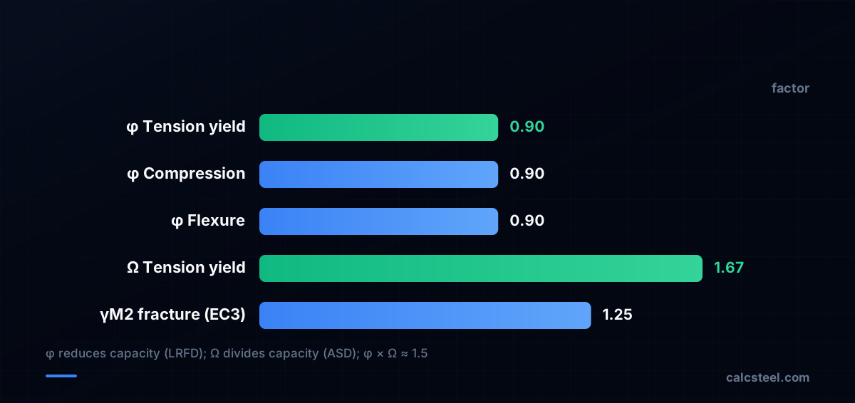
- AISC ties the two formats together: the ASD safety factor Ω ≈ 1.5/φ, so φ = 0.90 in LRFD corresponds to Ω = 1.67 in ASD for the same yielding limit state.
- Eurocode 3 uses recommended partial factors γM0 = 1.00, γM1 = 1.00 and γM2 = 1.25 (National Annexes may override); the right value depends on whether the limit state is cross-section, member stability or fracture.
- Each limit state carries its own factor — software like CalcSteel selects the correct φ, Ω or γM automatically per check, which is the only reliable way to stay consistent.
The question every steel engineer asks first
Open any steel project and the first instinct is to ask for a single number: how much margin do I leave? A century ago the honest answer was a single factor of safety applied to material strength — allowable stress was simply yield divided by a chosen number. In the United States, Allowable Stress Design (ASD) traces back to AISC's first specification of 1923, and its appeal is obvious: one factor, one calculation, easy to defend.
The trouble is that loads and resistances are uncertain in different ways. A factory live load is far more variable than the self-weight of a beam, and a brittle bolt fracture is far less forgiving than a ductile yield. A single number cannot honestly cover both. The history of safety factors is the history of engineers refusing to pretend it can.

From one number to a reliability target
The shift came from probability. In 1978, T. V. Galambos and M. K. Ravindra published the component-reliability methodology behind Load and Resistance Factor Design (LRFD), the end product of a research program at Washington University in St. Louis sponsored by the American Iron and Steel Institute. Instead of one safety factor, they calibrated separate factors so that every member type reaches a consistent target reliability index β — widely reported as about β ≈ 3.0 for members over a 50-year service life, and higher (around 4.5) for connections, which should never be the weak link.
The first AISC LRFD Specification followed in 1986. The philosophy: factor up the loads, factor down the resistance, and prove that the probability of the demand exceeding the capacity is acceptably small. Eurocode and others adopted the same limit-state thinking, expressed through partial factors.

What the factors actually are
In LRFD the check is Ru ≤ φRn: the required strength from factored loads must not exceed the nominal resistance multiplied by a resistance factor φ ≤ 1. For ductile tension yielding, φ = 0.90. The companion load combination is the familiar 1.2D + 1.6L — dead load amplified less than the more variable live load.
In ASD the check is Ra ≤ Rn/Ω: service-level load effects must not exceed nominal resistance divided by a safety factor Ω ≥ 1. For yielding, Ω = 1.67. The two are deliberately linked — AISC sets Ω ≈ 1.5/φ, so 1.5 / 0.90 ≈ 1.67, and for net-section rupture 1.5 / 0.75 = 2.0. Same physics, same calibration, two formats.
- φ (LRFD): reduces capacity; smaller for less-ductile or harder-to-predict limit states.
- Ω (ASD): divides capacity; the reciprocal-scaled twin of φ.
- γ (Eurocode/IS): partial factors split between actions (γF) and resistance (γM).
The same idea, four dialects
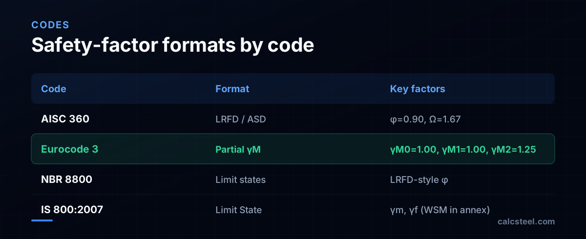
Every major code now speaks limit states, but the labels differ. AISC 360 (USA) carries both ASD and LRFD in a single document since the 2005 unification — that is when "Allowable Stress Design" was renamed Allowable Strength Design so both methods could share the same nominal-strength equations.
Eurocode 3 (EN 1993-1-1) uses partial factors on resistance: the recommended values are γM0 = 1.00 for cross-section resistance, γM1 = 1.00 for member instability, and γM2 = 1.25 for fracture and for bolts and welds — though National Annexes may override these (the UK Annex, for example, uses γM2 = 1.10). NBR 8800:2008 (Brazil) follows the LRFD-style limit-state format closely. IS 800:2007 (India) moved the country to the Limit State Method, retaining the older Working Stress Method only in an annex for legacy projects.
Why this belongs in software, not a lookup table
Here is the practical trap: there is no one safety factor to apply. A single beam check might use φb = 0.90 for flexure, φv = 0.90 (or 1.00 for certain webs) for shear, and a different φ for net-section rupture — and the governing limit state changes with slenderness, bracing and load ratio. Pick the wrong factor for the wrong limit state and the "margin" you think you have is fiction.
That is exactly the bookkeeping computers do well. The engineer chooses the code and the design situation; the tool selects the correct φ, Ω or γM for each check, applies the matching load combination, and reports the governing utilization. The factor is no longer a number you remember — it is a property of the limit state the software is evaluating.

The honest answer to the original question
So, what safety factor should you apply for steel design? The disciplined answer is: none of your own choosing. Adopt a code, identify the design situation, and let each limit state bring its own calibrated factor — φ and Ω in AISC 360, γM in Eurocode 3 and IS 800, the LRFD-style factors in NBR 8800. The numbers were already chosen by people who solved the probability problem so you do not have to re-solve it per project.
CalcSteel is a browser-native structural tool (React/TypeScript front-end, Python finite-element backend) with a free plan and Pro reported at US$24/month billed annually, 1,140+ steel profiles, and code checks for NBR 8800, AISC 360, Eurocode 3 and IS 800. It applies the correct factor per limit state automatically, so the safety margin you report is the one the code intends — not the one you half-remembered. You can try it directly in the editor.
Sources
- 1.The Evolution of Structural Design Specifications in the United States — STRUCTURE magazine
- 2.Load and Resistance Factor Design — T. V. Galambos (AISC)
- 3.Technical Note: Determination of Allowable Strength Design Safety Factors in the 2005 AISC Specification — AISC Engineering Journal
- 4.Safety Factors γM0 and γM1 in Metal Eurocodes — Baláž (Engineering Mechanics)
- 5.LRFD vs ASD — SkyCiv Engineering
- 6.Limit State Design: IS 800:2007 — A New Challenge for Structural Engineers in India
- 7.Image: SSJF01 — CC0 (Wikimedia Commons)
Try CalcSteel for free
Model, analyze and design steel structures in your browser. No install, no signup.
Open the 3D editor