Mohr's Circle and Principal Stress: The Criterion Behind the Code, With a Worked Check
No steel code limits your largest normal stress, and none limits your largest shear stress on its own. Both codes limit something you cannot read straight off a member: an equivalent stress built from the two principal stresses at a point. Mohr's circle is the geometry that turns the state you can measure, a normal stress and a shear stress acting together, into the principal stresses the criterion actually needs. Here is that criterion worked on a real steel bracket, with the internal forces computed in the shipping CalcSteel FEM engine and the stress transformation checked against the same math the live Mohr calculator runs. The punchline is where it governs: not the extreme fibre everyone checks, but the web-flange junction, where the von Mises stress comes out about 20 percent higher.
Key takeaways
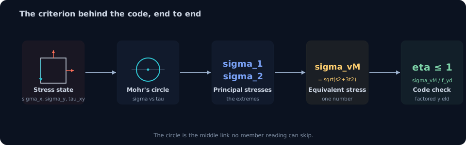
- The code criterion is an equivalent stress, not a raw one. EN 1993-1-1, NBR 8800 and AISC 360 all check a distortion-energy (von Mises) or max-shear (Tresca) demand built from the principal stresses, so neither the largest normal stress nor the largest shear stress alone is the thing you verify.
- Mohr's circle is the fast route to the principal stresses. From a plane-stress point (sigma_x, sigma_y, tau_xy) the circle gives sigma_1 and sigma_2 directly: centre = (sigma_x + sigma_y)/2, radius R = tau_max, and sigma_1,2 = centre plus or minus R.
- For a beam fibre the von Mises stress collapses to a clean shortcut. With sigma_y = 0 it becomes sigma_vM = sqrt(sigma^2 + 3 tau^2), which is exactly the combined-stress check in EN 1993-1-1 6.2.1(5).
- Worked on a real steel bracket (IPE 300 cantilever, L = 1.0 m, w = 120 kN/m). The FEM engine returns M = 60 kN.m and V = 120 kN at the fixed end. Extreme fibre: sigma = 107.7 MPa, von Mises 107.7 MPa. Web-flange junction: sigma = 100 MPa with tau = 47 MPa, von Mises 128.9 MPa.
- The governing point is the junction, not the extreme fibre. Its von Mises demand is 19.7 percent higher, because shear stacks onto bending through sqrt(sigma^2 + 3 tau^2). Check only the extreme fibre and you under-read the real utilization by about a fifth.
The code never checks your biggest stress
Open any steel standard to the clause that verifies yielding and you will not find a limit on the largest normal stress in a member, nor a separate limit on the largest shear stress. What the code limits is an equivalent stress: one number, built from the two principal stresses acting at a point, that stands in for the whole multiaxial state. A fibre with 100 MPa of bending and 47 MPa of shear is not verified against 100, and it is not verified against 47. It is verified against the equivalent stress those two produce together, and that number can be higher than either.
The gap between what you can read off a member and what the code actually checks is exactly the gap Mohr's circle closes. It takes the state you can compute, a normal stress and a shear stress on a face, and hands back the principal stresses the criterion needs. This article is not a tutorial on drawing the circle; for that, our companion guide on Mohr's circle from element to FEM walks every step. Here we stay on the criterion behind the code, and we work it on one real steel bracket, with the forces from the shipping CalcSteel FEM engine and the transformation checked to the decimal against the live calculator. The result is a lesson about where the check governs that a bending-only calculation never shows you.
The criterion: an equivalent stress, not a raw one
Steel yields by shape change, not by squeezing. Put a bar under equal pressure from every side (pure hydrostatic stress) and it barely yields at all; twist it, and it yields readily. That is the physical fact both leading yield criteria encode, and it is why the code limits an equivalent stress rather than any single component.
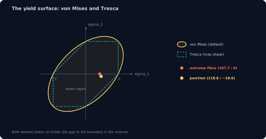
Von Mises (distortion energy) is the default in every modern steel code. For a plane-stress point it is sigma_vM = sqrt(sigma_1^2 − sigma_1 sigma_2 + sigma_2^2), where sigma_1 and sigma_2 are the principal stresses. Tresca (maximum shear) is the slightly more conservative alternative, sigma_Tr = sigma_1 − sigma_2 for the in-plane pair. Yielding starts when the equivalent stress reaches the yield strength f_y. Plotted in principal-stress space, von Mises is an ellipse and Tresca is a hexagon inscribed in it; any state inside the curve is elastic, any state on it is at first yield.
The codes write this the same way with different safety bookkeeping. EN 1993-1-1 6.2.1(5) states it for a beam fibre directly as sqrt(sigma^2 + 3 tau^2) ≤ f_y / gamma_M0. NBR 8800 5.4.2.2 limits the von Mises demand to f_y / gamma_a1 with gamma_a1 = 1.10. AISC 360 checks a stress state against phi f_y with phi = 0.90. Different letters, one idea: reduce the multiaxial state to an equivalent stress, then hold it below a factored yield. Everything else in this article is about getting that equivalent stress right, and Mohr's circle is how.
Mohr's circle in one minute: the geometry the criterion needs
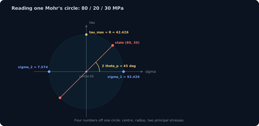
You only need four results from the circle to feed the criterion, so here they are on one plot. Take a plane-stress point with a normal stress on the x-face sigma_x, a normal stress on the y-face sigma_y, and a shear tau_xy. Plot sigma across and tau up. The circle is centred on the sigma-axis at sigma_avg = (sigma_x + sigma_y)/2 with radius R = sqrt(((sigma_x − sigma_y)/2)^2 + tau_xy^2).
From that circle the design numbers fall out geometrically: the two points where it crosses the sigma-axis are the principal stresses sigma_1 = sigma_avg + R and sigma_2 = sigma_avg − R; the top of the circle is the in-plane maximum shear tau_max = R; and the angle to the principal plane is tan(2 theta_p) = 2 tau_xy / (sigma_x − sigma_y). Angles double on the circle, so the plane of maximum shear always sits 45 degrees from the principal plane on the member.
A quick worked read, the calculator's default example: sigma_x = 80, sigma_y = 20, tau_xy = 30 MPa. Centre = 50, R = sqrt(30^2 + 30^2) = 42.426, so sigma_1 = 92.426, sigma_2 = 7.574 MPa, tau_max = 42.426 MPa at theta_p = 22.5 degrees. Its von Mises works out to 88.882 MPa, above sigma_1 alone, which is the whole point: the equivalent stress is not any single reading on the element. Now we put the circle to work on steel.
The worked check: a real steel bracket
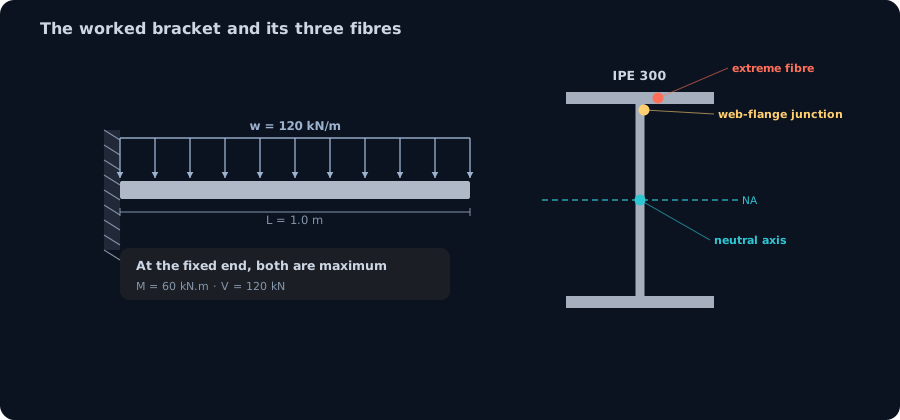
We want a member where bending and shear are both large at the same cross-section, because that is where the combined criterion earns its keep. A short cantilever bracket is exactly that case: at the fixed end the bending moment and the shear force are both at their maximum, on the same section. Think of a corbel carrying a heavy point of support, or a stub bracket off a column.
The bracket is an IPE 300, a cantilever of length L = 1.0 m, carrying a uniform load of w = 120 kN/m (a heavy short bracket, 120 kN total), in grade MR250 steel (f_y = 250 MPa). At the fixed end statics gives M = wL^2/2 = 60 kN.m and V = wL = 120 kN. We built this in the shipping CalcSteel FEM engine, the cantilever meshed into 24 elements, and it returns the reactions to the decimal: M = 60.000 kN.m and V = 120.000 kN. The internal forces are the engine's; from here the stress transformation is hand work, checked against the same routine the live calculator runs.
The IPE 300 section properties we use are the catalogue values an engineer looks up: area 53.8 cm^2, second moment of area I = 8356 cm^4, elastic section modulus W_el = 557 cm^3, web thickness 7.1 mm, flange thickness 10.7 mm. (The engine's own geometry routine returns I = 8097 cm^4 and W_el = 540 cm^3, about 3 percent below catalogue, which is the expected agreement for a computed section and does not move the story.) We now read the stress state at three fibres of that section, and let Mohr's circle tell us which one the code cares about.
Three fibres, three very different circles
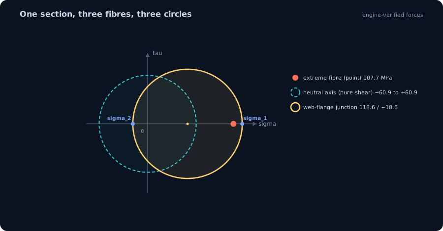
The same cross-section carries a different stress state at every height, so it draws a different Mohr's circle at every fibre. Three fibres tell the whole story.
The extreme fibre (flange tip). Bending is maximum, shear is zero. The state is uniaxial: sigma = M / W_el = 6000 kN.cm / 557 cm^3 = 10.77 kN/cm^2 = 107.7 MPa, tau = 0. The circle collapses to a point on the sigma-axis: sigma_1 = 107.7, sigma_2 = 0, and the von Mises stress equals the applied stress, 107.7 MPa. This is the point a flexure check looks at, and on its own it looks comfortable.
The neutral axis (mid-height). Bending is zero, shear is maximum. Using the exact VQ/It distribution the shear peaks at tau = 60.9 MPa (the code's simplified average, V divided by the web area, is 56.3 MPa). This is pure shear: the circle is centred on the origin, principal stresses are equal and opposite at sigma_1 = +60.9 and sigma_2 = −60.9 MPa, rotated 45 degrees off the axis, and the von Mises stress is sqrt(3) times the shear, 105.5 MPa. Still below the extreme fibre.
The web-flange junction. Just under the flange, both are large at once: bending is still 100 MPa (the fibre is near the extreme, at height 139.3 mm of the 150 mm half-depth) and the web carries a shear of 47 MPa there. Now the circle is a genuine circle with an offset centre: sigma_avg = 50 MPa, R = sqrt(50^2 + 47^2) = 68.6 MPa, so sigma_1 = 118.6, sigma_2 = −18.6 MPa, tau_max = 68.6 MPa, at theta_p = 21.6 degrees. The tension principal has climbed past the extreme-fibre value, and a compression principal has appeared out of nowhere. That is the state the criterion is about to punish.
The junction governs, not the extreme fibre
Now feed each fibre's principal stresses into the von Mises criterion and the ranking flips against intuition:
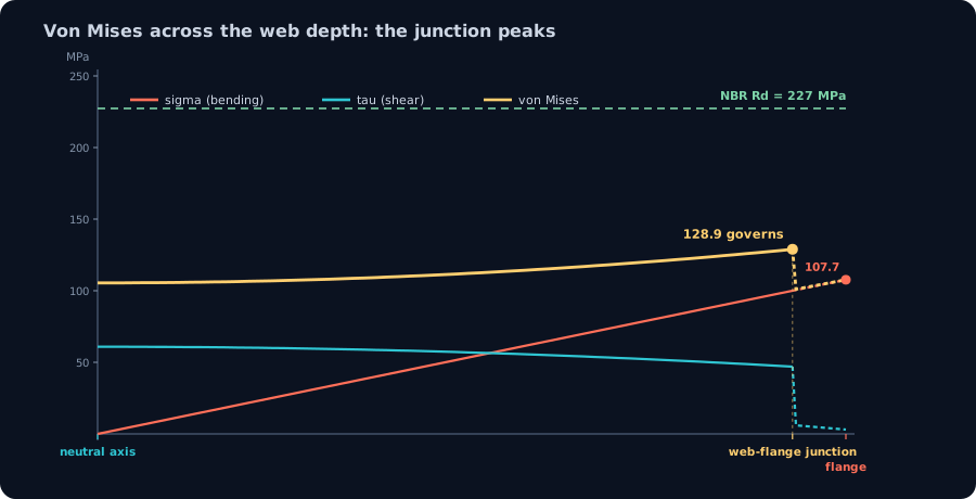
- Extreme fibre: sigma_vM = 107.7 MPa.
- Neutral axis: sigma_vM = 105.5 MPa.
- Web-flange junction: sigma_vM = 128.9 MPa.
The junction governs by 19.7 percent over the extreme fibre, even though its bending stress is lower and its shear stress is lower than the peaks elsewhere. The reason is the beam-fibre shortcut: with sigma_y = 0 the von Mises stress is exactly sigma_vM = sqrt(sigma^2 + 3 tau^2), so at the junction sqrt(100^2 + 3 × 47^2) = sqrt(10000 + 6627) = 128.9 MPa. Shear does not add to bending arithmetically; it adds under a square root with a factor of three, and the maximum of that sum lives at the web-flange junction, where bending is still near its peak and the web is carrying its full shear.
This is the entire practical value of the criterion. A flexure check reads 107.7 MPa at the extreme fibre and stops. A shear check reads the web shear and stops. Neither sees the 128.9 MPa the material actually feels at the junction. The combined-stress clause exists precisely because that peak is invisible to the two checks done separately, and Mohr's circle is what makes it visible: the junction circle is simply bigger than the other two.
Applying the criterion across three codes
With the governing demand fixed at 128.9 MPa and MR250 steel (f_y = 250 MPa), the three codes differ only in how they factor the resistance:
EN 1993-1-1 (gamma_M0 = 1.0): resistance 250 MPa, utilization at the junction eta = 128.9 / 250 = 0.52; at the extreme fibre 107.7 / 250 = 0.43.
NBR 8800 (gamma_a1 = 1.10): resistance 227.3 MPa, eta = 128.9 / 227.3 = 0.57; extreme fibre 0.47.
AISC 360 (phi = 0.90): resistance 225 MPa, eta = 128.9 / 225 = 0.57; extreme fibre 0.48.
Every code passes, comfortably, and that is fine, the bracket is not the point. The point is the spread between the two columns. In each code the true governing utilization is roughly 20 percent higher than the extreme-fibre number a bending-only check would report. On this bracket that is the difference between reading 47 percent utilised and reading 57 percent (NBR). On a section chosen closer to the limit it is the difference between a check that passes and one that does not. The criterion behind the code is not a formality; it decides the section whenever bending and shear are both significant on the same cut, which is the everyday condition at a cantilever root, a coped beam end, or an interior support of a continuous beam.
Try it: read the principal stresses and the code check live
The calculator below runs the same plane-stress transformation and yield check used above, live in your browser. Type the junction state, sigma_x = 100, sigma_y = 0, tau_xy = 47, and read sigma_1 = 118.6, sigma_2 = −18.6, tau_max = 68.6 and von Mises 128.9 MPa straight off the circle. Then drag the diameter and watch every number move together, or switch the yield check between NBR 8800 and AISC 360 and see the utilization shift with the safety factor.
It does more than the worked example needs. It loads a real solved section straight from the CalcSteel FEM model, so the circle becomes the inspection lens on your own analysis rather than a textbook exercise; it goes triaxial when the out-of-plane stress is not zero; and it exports the figure. It is free and needs no login for the transformation. Feed it the extreme fibre (100.02 becomes a point) and the junction in turn, and you will watch the governing circle grow in real time.
σ₁ (major)
92.4MPa
σ₂ (minor)
7.6MPa
τmax in-plane
42.4MPa
θp (to σ₁)
22.5°
τabs (3-D)
46.2MPa
von Mises
88.9MPa
η · NBR
0.28 ✓
Plane-stress state (MPa)
Tension positive. τxy positive = shear that tends to rotate the element counter-clockwise on the +x face.
Plane stress (σz = 0). Enable to inspect a genuine triaxial state — three circles, not two.
Code check — steel grade
σvM = 88.9 MPa ≤ 313.6 MPa = fy / γa1 (γa1 = 1.10)
NBR 8800:2008 §5.4.2.2 (γa1 = 1,10)
From your solved model
Solve a model in the CalcSteel 3D editor, then return here to load the real σx/σy/τxy at any member section — Mohr's circle becomes the solver's inspection lens.
Presets
Element rotation θ
0°Export (free · no watermark)
How to check a combined-stress result you did not hand-solve
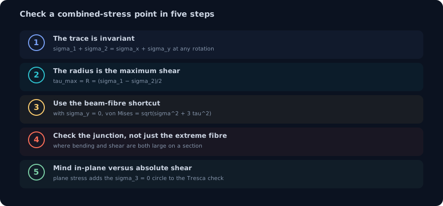
You will let the solver and the calculator produce the numbers. The skill worth keeping is auditing them, and Mohr's circle gives you fast invariants to audit against. Five checks catch almost every error on a combined-stress verification.
1. The trace is invariant. sigma_1 + sigma_2 must equal sigma_x + sigma_y, at any rotation. If the principal stresses do not sum back to the original normal stresses, the transformation is wrong. For the junction: 118.6 + (−18.6) = 100, which is sigma_x + 0.
2. The radius is the maximum shear. tau_max = R = (sigma_1 − sigma_2)/2. Junction: (118.6 + 18.6)/2 = 68.6 MPa. If a reported tau_max is not half the spread of the principal stresses, something is off.
3. For a beam fibre, use the shortcut. With sigma_y = 0, von Mises must equal sqrt(sigma^2 + 3 tau^2). It is a one-line hand check on any solver output at a bending-plus-shear point, and it is literally the EN 1993-1-1 clause.
4. Check the junction, not just the extreme fibre. Where bending and shear are both significant on a section, inspect the web-flange junction. If your only stress check is at the extreme fibre, you are structurally blind to the governing point.
5. Mind in-plane versus absolute shear. The circle you draw gives the in-plane tau_max. The absolute maximum shear that governs a Tresca check includes the out-of-plane principal (sigma_3 = 0 in plane stress), so it can be larger, (sigma_1 − sigma_3)/2. For the junction that is 118.6/2 = 59.3 MPa, larger than a naive reading of the drawn circle's crown minus the offset.
Common mistakes and FAQ
Checking the extreme fibre only. The single most common combined-stress error. The extreme fibre is where bending peaks but shear is zero, so it hides the junction, where the von Mises demand here was 19.7 percent higher. Wherever M and V are both large on a section, the extreme fibre is not the governing point.
Adding sigma and tau arithmetically. Stresses on different faces do not add like scalars. 100 MPa of bending and 47 MPa of shear are not 147 MPa of anything. They combine through the circle into principal stresses, and the von Mises demand is 128.9 MPa, not 147 and not 100.
Confusing von Mises and Tresca. Tresca (max shear) is always the more conservative of the two, by up to about 15 percent in pure shear. Codes default to von Mises; if a check uses sigma_1 − sigma_2 it is Tresca, and it will read a little heavier. Both are legitimate; just know which one produced the number.
Where would sigma_y ever be non-zero in a beam? At bearing and under concentrated loads, where transverse compression is real, and in plates and shells generally. A simple beam fibre is plane stress with sigma_y near zero, which is why the sqrt(sigma^2 + 3 tau^2) shortcut works so often, but the full circle is there for when it does not.
Plane stress or plane strain? A free surface fibre of a beam or column is plane stress (the out-of-plane stress is zero). Deep inside a thick body it can be closer to plane strain, which changes the out-of-plane principal and therefore the absolute maximum shear. For steel members the plane-stress reading is the right default.
Do I still need Mohr's circle if the solver reports von Mises directly? As a check, yes. It is the one-line geometry that confirms the solver's principal stresses are consistent (trace invariant, radius equals tau_max) before you trust the equivalent stress it built from them.
Key takeaways
- No steel code limits your largest normal or shear stress on its own. EN 1993-1-1, NBR 8800 and AISC 360 all limit an equivalent stress, von Mises by default, built from the principal stresses.
- Mohr's circle produces those principal stresses from a plane-stress point: centre (sigma_x + sigma_y)/2, radius R = tau_max, sigma_1,2 = centre plus or minus R, principal plane at tan(2 theta_p) = 2 tau_xy / (sigma_x − sigma_y).
- For a beam fibre the criterion collapses to sigma_vM = sqrt(sigma^2 + 3 tau^2), which is exactly EN 1993-1-1 6.2.1(5). It is the fastest hand check you have on any combined-stress point.
- Worked on an IPE 300 cantilever bracket with the FEM engine (M = 60 kN.m, V = 120 kN): extreme fibre 107.7 MPa, neutral axis 105.5 MPa, web-flange junction 128.9 MPa. The junction governs by 19.7 percent.
- Check the junction, not just the extreme fibre, whenever bending and shear are both significant on a section: a cantilever root, a coped beam, an interior support. That is the point the criterion behind the code was written to catch.
Sources
- 1.Gere and Goodno, Mechanics of Materials (plane stress, Mohr's circle, principal stresses)
- 2.Boresi and Schmidt, Advanced Mechanics of Materials (von Mises and Tresca yield criteria)
- 3.Eurocode EN 1993-1-1, Design of steel structures: General rules, 6.2.1 (combined stress, sqrt(sigma^2 + 3 tau^2))
- 4.AISC 360, Specification for Structural Steel Buildings (yielding of a stress state)
- 5.ABNT NBR 8800, Projeto de estruturas de aco e de estruturas mistas de aco e concreto, 5.4.2.2
Try CalcSteel for free
Model, analyze and design steel structures in your browser. No install, no signup.
Open the 3D editor