Load Combinations: Why 1.2D + 1.6L Governs
No single load acts alone: gravity, wind, snow, and seismic forces overlap in ways the structure must survive. Load combinations are the code's recipe for adding them up safely. ASCE 7 defines seven LRFD combinations and nine ASD combinations — but in practice, just two or three govern 90% of steel designs. Here is how they work, why the factors differ, and how CalcSteel automates all of them.
Key takeaways
- Load combinations ensure the structure can survive all realistic combinations of dead, live, wind, snow, and seismic loads acting simultaneously.
- LRFD factors loads UP (1.2D + 1.6L) and capacity DOWN (φ = 0.9). ASD uses unfactored loads and a single safety factor (Ω = 1.67). Both give similar results for typical buildings.
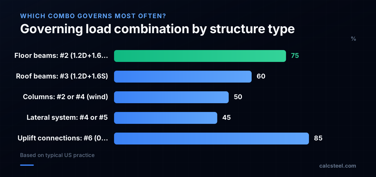
- For floor beams, combo #2 (1.2D + 1.6L) governs ~75% of the time. For uplift connections, combo #6 (0.9D + 1.0W) is almost always critical.
- CalcSteel generates all ASCE 7/NBR 8681/EN 0 combinations automatically from the load cases you define — including the companion-load factors and load direction signs.
What are load combinations in structural design?
A building is never loaded by just dead weight. At any moment it carries some combination of dead load (self-weight of the structure and permanent attachments), live load (people, furniture, equipment), wind, snow or rain, and possibly seismic forces. The question is: which combination of these loads is the worst case?
You cannot simply add every load at its maximum — the probability that full live load, maximum wind, peak snow, and a design earthquake all happen simultaneously is vanishingly small. Load combinations are the code's answer: they prescribe how to superimpose different load types with appropriate load factors that reflect each load's variability and the probability of co-occurrence.
In the United States, load combinations come from ASCE 7 (Minimum Design Loads for Buildings). In Brazil, from NBR 8681. In Europe, from EN 1990 (Eurocode 0). The specific factors differ, but the logic is the same: the structure must be checked against every prescribed combination, and the worst-case combination governs the design.
Software like CalcSteel generates all combinations automatically once you define your load cases (dead, live, wind X, wind Y, snow, etc.). The program solves every combination, envelopes the results, and reports the governing combination for each member and each limit state.

What is the difference between LRFD and ASD load combinations?
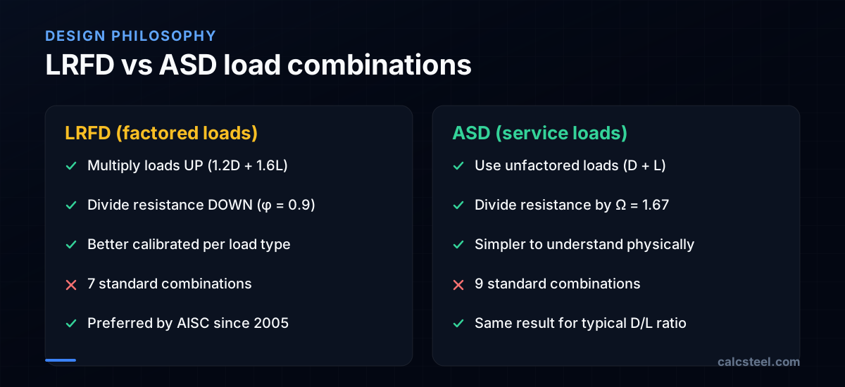
ASCE 7 provides two parallel sets of load combinations: LRFD (Section 2.3) with seven combinations and ASD (Section 2.4) with nine combinations. Both are equally valid — AISC 360 supports both — but they reflect different design philosophies.
LRFD (Load and Resistance Factor Design) multiplies each load type by a different factor (1.2 for dead, 1.6 for live, 1.0 for wind/seismic, 0.5 for companion loads) and then divides the resistance by φ (0.9 for flexure, 0.75 for bolts, etc.). The variable factors capture the idea that live load is less predictable than dead load — it deserves a higher factor.
ASD (Allowable Stress Design) uses unfactored loads (or loads with factors close to 1.0) and divides the resistance by a single safety factor Ω (1.67 for flexure). The ASD factors for wind and seismic are 0.6W and 0.7E — these were recalibrated in ASCE 7-10 to make ASD and LRFD give the same result for typical cases.
The practical difference: LRFD design loads are ~40% higher than ASD for gravity-only cases (1.2 + 1.6 vs 1.0 + 1.0), but the LRFD resistance is only divided by 1/0.9 ≈ 1.11 vs ASD's 1/1.67. The product φ × Ω = 0.9 × 1.67 = 1.5 ensures both methods converge.
What are the ASCE 7 load combinations?
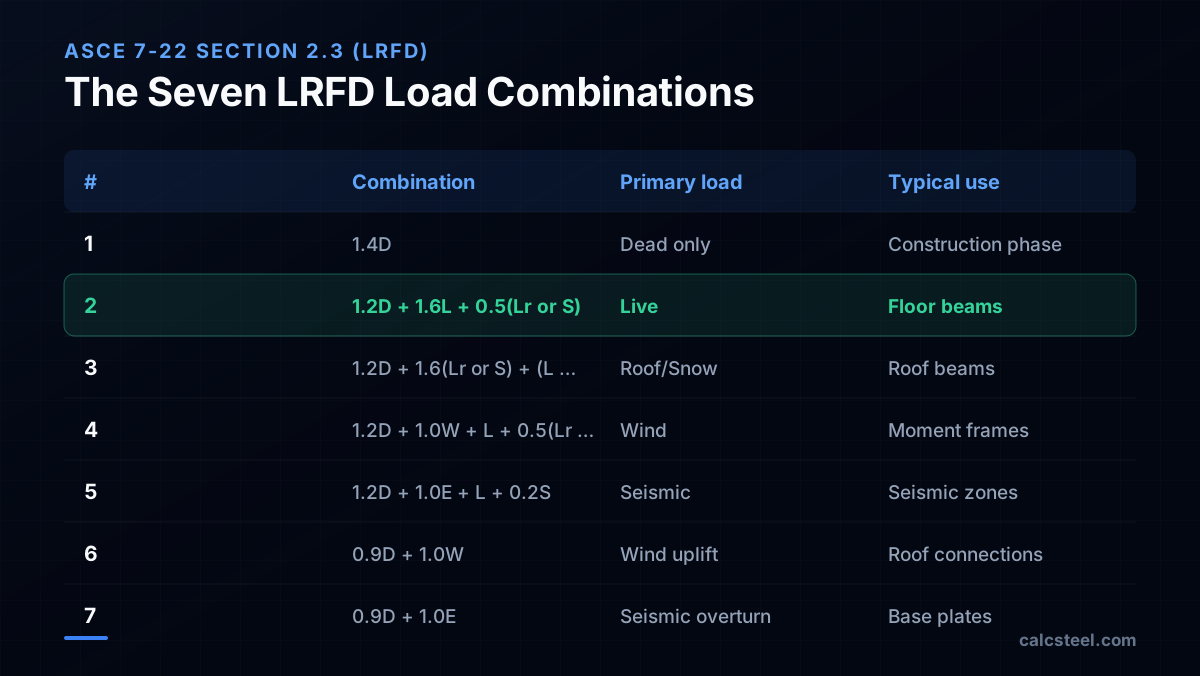
The seven LRFD combinations from ASCE 7-22 Section 2.3.1 are the backbone of US structural design. Every steel building designed to AISC 360 uses these (or their equivalent in other codes). Here they are, with commentary on when each governs:
- 1.4D — Dead load only. Governs during construction before live load is applied, or for structures with very high dead-to-live ratio (massive concrete roofs).
- 1.2D + 1.6L + 0.5(Lr or S or R) — The gravity king. This is the combination that sizes most floor beams and interior columns. The 1.6 factor on live load dominates.
- 1.2D + 1.6(Lr or S or R) + (L or 0.5W) — Governs roof beams in snow country. The primary load is roof live load or snow, with companion live or wind.
- 1.2D + 1.0W + L + 0.5(Lr or S or R) — Wind governs. This sizes lateral-force-resisting systems (braces, moment frames) and columns in tall buildings.
- 1.2D + 1.0E + L + 0.2S — Seismic governs. Critical in seismic design categories D, E, F. The earthquake load E already includes redundancy and overstrength factors.
- 0.9D + 1.0W — Wind uplift. Minimum dead load + wind suction. This combination is critical for roof connections, hold-down straps, and light structures where wind can lift the roof.
- 0.9D + 1.0E — Seismic overturning. Minimum dead load + seismic. Critical for foundation design (overturning) and base plate anchorage.
Notice that combinations #6 and #7 use 0.9D instead of 1.2D. This is intentional: when dead load helps (by resisting uplift or overturning), you use its minimum value — it would be unconservative to assume more dead load than actually exists.
How to combine dead load and live load?
For the most common case — a floor beam with dead load and live load only — the LRFD combination is straightforward:
U = 1.2D + 1.6L
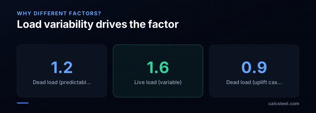
where U is the factored load effect (moment, shear, or reaction). Dead load gets a factor of 1.2 (it is relatively predictable — self-weight does not vary much) and live load gets 1.6 (it is highly variable — a crowded event space can have double the design live load).
Worked example: A W410×60 floor beam spans 8 m with D = 10 kN/m (slab + beam self-weight) and L = 15 kN/m (office occupancy at 3 m tributary width × 5 kN/m²).
- Factored uniform load: wu = 1.2 × 10 + 1.6 × 15 = 12 + 24 = 36 kN/m
- Factored moment: Mu = wuL²/8 = 36 × 8²/8 = 288 kN·m
- Beam capacity: φMn = 370 kN·m (W410×60, fully braced). Ratio = 288/370 = 0.78 ✓
For serviceability (deflection), use unfactored service loads: δ = 5wL⁴/(384EI) with wL = 15 kN/m (live load only for L/360 check) or wtotal = 25 kN/m (for L/240 check).
The critical distinction: strength checks use factored loads, deflection checks use unfactored loads. Mixing them up is one of the most common errors in practice.
What is a load factor in structural engineering?
A load factor is a multiplier applied to a load type to account for the uncertainty in its magnitude. The concept was developed in the 1960s–1970s as part of the reliability-based design movement, led by researchers like C. Allin Cornell and Bruce Ellingwood.
The idea is simple: loads we know well (dead load) get a small factor, loads we know poorly (live load) get a larger factor. The factors were calibrated using probabilistic analysis so that the resulting designs have a target reliability index β ≈ 2.5–3.0 (corresponding to a failure probability of roughly 1 in 1000 to 1 in 10,000 over the building's lifetime).
Key load factors in ASCE 7 LRFD:
- 1.4 for dead load alone — used only when no other loads are present.
- 1.2 for dead load when combined with other loads — reflects that dead load is relatively well-known (±10% variation).
- 1.6 for live load — reflects high variability (live load can range from near-zero to twice the design value).
- 1.0 for wind and seismic — these loads already include their own probabilistic factors (return period, importance factor).
- 0.5 for companion loads — loads that act simultaneously but are unlikely to be at their maximum at the same time as the primary load.
- 0.9 for dead load in uplift/overturning — the minimum credible dead load, because dead load helps resist these effects.
The resistance factor φ works on the other side: it accounts for uncertainty in material strength, fabrication tolerances, and the analysis model. Together, load factors and resistance factors achieve a uniform level of safety.
When does wind load govern the design?
Wind governs the design of the lateral-force-resisting system (LFRS) in most buildings — the braces, moment frames, or shear walls that resist horizontal forces. Specifically, wind becomes critical when:
- The building is tall relative to its width. Wind moment at the base scales with height², so a 20-storey building has 4× the base overturning moment of a 10-storey building with the same wind speed.
- The building has a large exposed area. Wide facades collect more wind pressure. This is why long warehouse walls need wind bracing even though the structure is low-rise.
- The roof is lightweight. Wind uplift (negative pressure on the roof) acts upward. If the dead load is small (metal roof, no concrete), the net uplift can be significant, making combo #6 (0.9D + W) govern the roof connections.
- The seismic demand is low. In low-seismic regions, wind almost always governs the lateral design. In high-seismic regions (SDC D, E, F), earthquake loads typically exceed wind.
ASCE 7 combination #4 is the wind-governs combo: 1.2D + 1.0W + L + 0.5(Lr or S). The wind factor is 1.0 (not 1.6) because ASCE 7 wind speeds are already based on the ultimate-event return period (700-year MRI for Risk Category II). The companion loads (L, Lr, S) are at 50% or less because maximum wind and maximum live load are unlikely to coincide.
In CalcSteel, you define wind load cases (pressure on windward, suction on leeward) and the software automatically creates all wind-containing combinations. The envelope of all combinations highlights where wind governs — typically in the lateral braces and the columns at the windward face.

How does CalcSteel handle load combinations?
CalcSteel automates the entire load combination process. Here is the workflow:
Step 1 — Define load cases. Create individual load cases for each load type: Dead (D), Live (L), Roof Live (Lr), Wind X (Wx), Wind Y (Wy), Snow (S), Seismic X (Ex), Seismic Y (Ey). Each case contains the loads for that type only.
Step 2 — Select the code. Choose your design standard (AISC 360, NBR 8800, Eurocode 3) and the load combination standard (ASCE 7, NBR 8681, EN 1990). CalcSteel generates all prescribed combinations automatically — including the correct load factors, companion factors, and sign variations for reversible loads (wind, seismic).
Step 3 — Run the analysis. CalcSteel solves every combination and creates the load envelope: the maximum and minimum of each internal force (moment, shear, axial) across all combinations, at every point along every member.
Step 4 — Read the results. The design verification uses the envelope values. For each member and each limit state, CalcSteel reports:
- The governing combination (e.g., "LC 2: 1.2D + 1.6L")
- The utilisation ratio (demand/capacity)
- Whether strength or serviceability governs
You never need to manually list combinations, multiply loads by factors, or worry about missing a combination. The software handles the bookkeeping; you focus on engineering judgement: Are the load magnitudes correct? Are the load paths realistic? Does the envelope make physical sense?

Load combination calculation step by step
Let us apply all seven LRFD combinations to a roof beam spanning 10 m with the following service loads: D = 5 kN/m, Lr = 3 kN/m (roof live), Wup = −4 kN/m (wind uplift on roof), S = 2 kN/m (snow). The beam is a W360×33.
Combo 1: 1.4D = 1.4 × 5 = 7.0 kN/m. M = 7.0 × 10²/8 = 87.5 kN·m.
Combo 2: 1.2D + 1.6L + 0.5Lr = 1.2×5 + 1.6×0 + 0.5×3 = 7.5 kN/m. M = 93.8 kN·m. (Note: L = 0 for a roof.)
Combo 3: 1.2D + 1.6Lr + 0.5W = 1.2×5 + 1.6×3 + 0.5×(−4) = 6 + 4.8 − 2 = 8.8 kN/m. M = 110 kN·m. ← governs for downward moment.
Combo 4: 1.2D + 1.0W + 0.5Lr = 1.2×5 + 1.0×(−4) + 0.5×3 = 6 − 4 + 1.5 = 3.5 kN/m. M = 43.8 kN·m.
Combo 6: 0.9D + 1.0W = 0.9×5 + 1.0×(−4) = 4.5 − 4 = 0.5 kN/m. M = 6.3 kN·m. If wind uplift were stronger (say −6 kN/m), this combination would produce net uplift (negative reaction), requiring hold-down connections.
Governing: Combo 3 at Mu = 110 kN·m. W360×33 capacity: φMn = 0.9 × 345 × 481 × 10³/10⁶ = 149 kN·m. Ratio = 110/149 = 0.74 ✓.
The key insight: for this roof beam, combo #3 (roof live load + wind) governs, not the simple gravity combo #2. Missing this combination would under-design the beam. CalcSteel checks all seven automatically, so no combination is ever skipped.

Sources
- 1.ASCE 7-22: Minimum Design Loads for Buildings (Chapter 2: Combinations)
- 2.AISC 360-22 Specification for Structural Steel Buildings
- 3.NBR 8681:2003 — Ações e segurança nas estruturas (Combinações)
- 4.EN 1990:2002 (Eurocode 0) — Basis of structural design (Combinations of actions)
- 5.Ellingwood et al., Development of a Probability-Based Load Criterion (NBS SP577)
- 6.SkyCiv: Load Combinations — ASCE 7 Guide
- 7.STRUCTURE Magazine: Understanding ASCE 7 Load Combinations
- 8.r/StructuralEngineering: Load combinations confusion (Reddit)
Try CalcSteel for free
Model, analyze and design steel structures in your browser. No install, no signup.
Open the 3D editor