Import Revit, AutoCAD & SAP2000: What Transfers

"Can I import my existing model from Revit, AutoCAD or SAP2000?" is really two questions in one: can the geometry come across, and does the engineering survive with it? The honest answer depends entirely on which interchange format you choose — and those formats were each born for a different job, decades apart.
Key takeaways
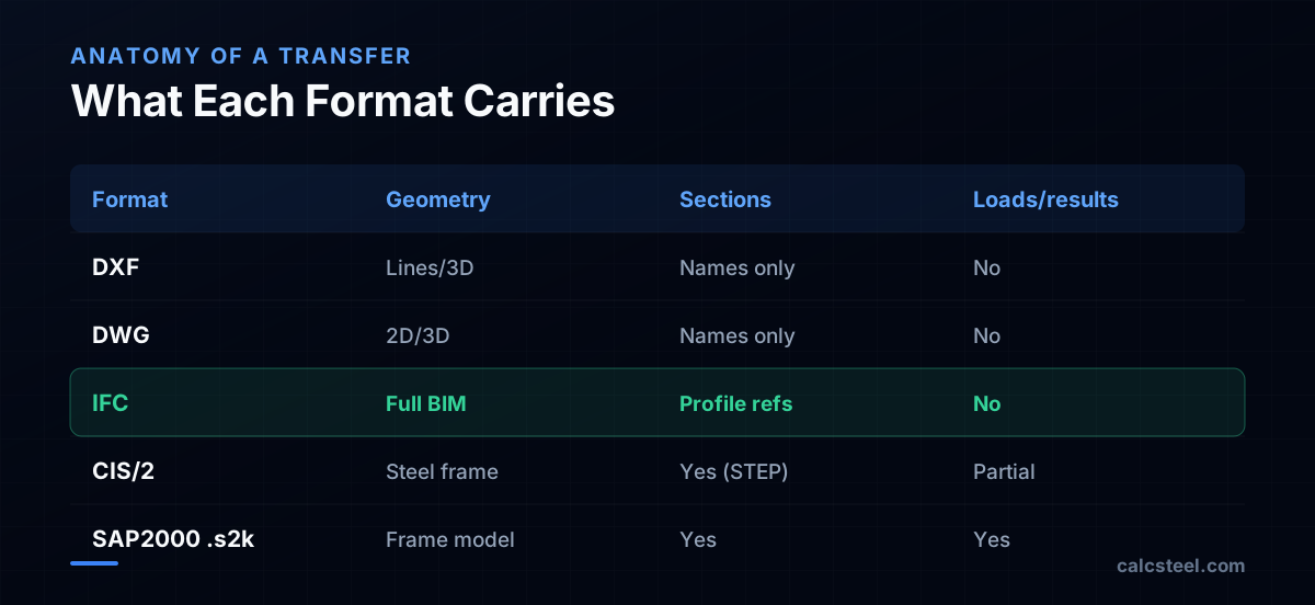
- DXF (1982) and DWG carry geometry and section names, but no loads, releases, or results — they are drawing formats, not analysis models.
- IFC (first published June 1996, now ISO 16739-1:2024) is the vendor-neutral BIM standard; CIS/2 is the steel-specific STEP-based format endorsed by AISC.
- SAP2000's native files preserve the most engineering data — but only between analysis tools that speak the same dialect.
- No format is fully lossless: geometry transfers reliably, engineering intent (load combinations, end fixity, code checks) rarely does.
It Is Two Questions, Not One
When engineers ask whether a model can be imported, they usually picture a single button that reconstructs everything: the frame, the loads, the supports, the verified members. In practice, model exchange is layered. Geometry — nodes and member centerlines — is the easy part and travels through almost any format. Section assignments travel as text labels that the receiving tool must recognize. Engineering intent — load cases, combinations, end releases, support conditions, and especially analysis results — is the part that breaks.
Understanding why means understanding where each format came from. A format built to plot drawings in 1982 was never designed to carry a load combination. A format built to coordinate a whole building never standardized how a beam end is released. Knowing the lineage tells you exactly what to expect when you press Import.
DXF and AutoCAD: The 1982 Drawing Layer
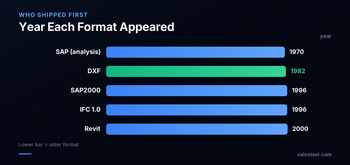
AutoCAD debuted at the COMDEX show in Las Vegas in November 1982 and was released that December — one of the first CAD programs to run on a personal computer. Autodesk had been founded earlier that same year (January 30, 1982) by John Walker together with a group of programmers who, by Walker's own account in The Autodesk File, pooled roughly US$59,000 to start the company. Alongside AutoCAD 1.0 came DXF (Drawing Interchange Format), introduced specifically so drawings could move between the incompatible hardware platforms of the early 1980s.
That origin defines its limits. DXF and the native binary DWG format describe entities you can draw: lines, polylines, arcs, 3D faces, layers, and text. A member section is, at best, a layer name or a block label — there is no concept of a load, a support, or a stress ratio. AutoCAD later gained programmability through AutoLISP (introduced January 1986, in AutoCAD version 2.18), but the underlying model stayed a drawing database. So importing a DXF gives you accurate lines to trace your structure onto — a real head start — but you will re-enter every boundary condition and load by hand.

Revit, BIM and the Rise of IFC
Revit came from a startup called Charles River Software, founded in Newton, Massachusetts on October 31, 1997 by Leonid Raiz and Irwin Jungreis, two former lead developers of PTC's Pro/Engineer. Their pitch was a parametric building model that updated instantly — the name Revit is a contraction of "Revise-Instantly." The company was renamed Revit Technology Corporation in January 2000, shipped Revit 1.0 that year, wrote it in C++, and was acquired by Autodesk for a reported US$133 million in 2002.
Revit is a Building Information Model, not a structural analysis model. To move a BIM between vendors, the industry built IFC (Industry Foundation Classes). The effort began in 1994 as an Autodesk-led consortium of US companies, opened to all members in September 1995 as the Industry Alliance for Interoperability, was renamed the International Alliance for Interoperability in 1996, and published IFC 1.0 in June 1996; the body became buildingSMART in 2005. Today IFC is the official international standard ISO 16739-1:2024, with its file encoding built on the STEP family (ISO 10303-21). IFC carries the full building — walls, slabs, beams, grids, levels, materials — so an IFC import reconstructs your frame faithfully. What it does not standardize well is analysis data: loads and results are out of scope for the core building model.
SAP2000 and CIS/2: Where Engineering Lives
The analysis world has the oldest roots. The original SAP — Structural Analysis Program — was developed by Dr. Edward L. Wilson at UC Berkeley around 1970, a landmark in finite-element software. Ashraf Habibullah founded Computers and Structures, Inc. (CSI) in Berkeley in 1975 to commercialize that lineage. SAP2000, first released in 1996, was the first version of SAP fully integrated within Microsoft Windows with a graphical interface.
Because SAP2000 is an analysis tool, its native and text (.s2k) files carry what drawing formats cannot: joints, frame elements, releases, restraints, load patterns, load combinations, and results. The catch is that these are best preserved between analysis tools that agree on the conventions. For steel specifically, the industry standardized CIS/2 (CIMsteel Integration Standards), created by the Steel Construction Institute in the UK and built on STEP (ISO 10303). CIS/2 Release 2 was endorsed by the American Institute of Steel Construction as the standard for the electronic exchange of structural-steel project information in North America, and it can carry analysis, design, and fabrication views of a steel frame — far richer than DXF for steelwork.

A Practical Import Strategy
Match the format to the goal:
- You have a Revit/CAD drawing and want to model fast: export DXF (or IFC for richer 3D context) and use it as an accurate tracing layer. Expect to define supports and loads yourself.
- You are moving a steel frame between fabrication and analysis: CIS/2 preserves the most steel-specific intent.
- You are moving between analysis packages: native or text formats keep loads and combinations, but verify every release and restraint after import — conventions differ.
Whatever the path, treat import as a head start, not a finished model. The single most common error is trusting that loads or end conditions came across when they did not. Re-check supports, releases, load cases, and section recognition before you run a single analysis. Geometry is cheap to trust; engineering intent must be re-verified.

The Verdict — and Where CalcSteel Fits
So, can you import an existing model? Geometry: yes, reliably, through DXF, DWG or IFC. Engineering intent: only partially, and only through analysis-grade formats — and even then you must re-verify. No format is magic; each was designed for a different decade and a different job.
CalcSteel is a browser-native structural tool — a React/TypeScript front end over a Python finite-element backend — with a free plan and Pro at US$24/month billed annually. It ships 1,140+ steel profiles and runs code checks against NBR 8800, AISC 360, Eurocode 3 and IS 800. The fastest workflow today is to bring in your geometry through DXF or IFC as a tracing base, then rebuild supports, loads and combinations natively so every result is one you verified — not one you inherited.
Sources
- 1.AutoCAD — Wikipedia (history, COMDEX 1982, DXF)
- 2.Autodesk Revit — Wikipedia (Charles River Software, 1997, US$133M)
- 3.Industry Foundation Classes — Wikipedia (IAI, 1996, ISO 16739-1)
- 4.buildingSMART — Wikipedia (IAI history, 2005 rename)
- 5.SteelVis (aka CIS/2 Viewer) — NIST (CIS/2, STEP, AISC endorsement)
- 6.AutoLISP — Wikipedia (introduced 1986, AutoCAD 2.18)
- 7.John Walker (programmer) — Wikipedia (Autodesk founding, The Autodesk File)
- 8.Image: Santiago Gomez iamsantiago — CC0 (Wikimedia Commons)
Try CalcSteel for free
Model, analyze and design steel structures in your browser. No install, no signup.
Open the 3D editor