Steel Warehouse Design: Portal Frame Tutorial

Short answer: in CalcSteel you sketch the portal frame geometry, apply gravity and wind loads, let the engine build the factored combinations and force envelope, then verify a trial section against your code (NBR 8800, AISC 360, Eurocode 3 or IS 800) and read the utilization ratio. This guide does exactly that for a worked example - a 30 m clear-span shed - and then explains the portal frame, the plastic theory behind its economy, and how CalcSteel compares with the desktop tools it replaces.
Key takeaways
- To design a single-span warehouse you follow one loop in any code: set the portal geometry, apply dead, live, snow and wind, build factored combinations, take the force envelope, then verify each member and connection.
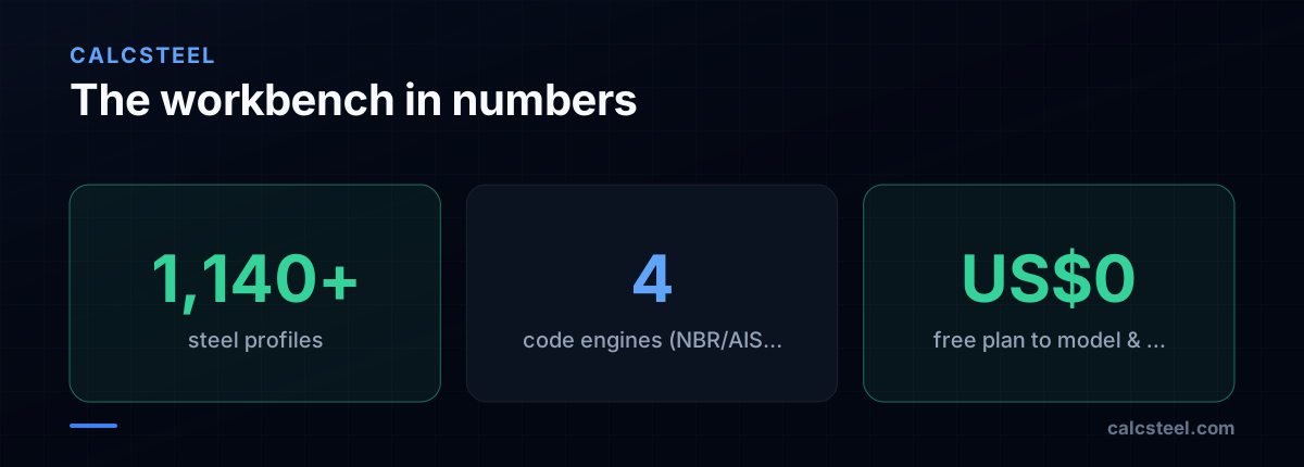
- CalcSteel runs that whole loop in the browser with 1,140+ steel profiles and code engines for NBR 8800, AISC 360, Eurocode 3 and IS 800 - on a free plan, with Pro at US$24/month (billed annually) for heavier exports.
- The single-span pitched portal frame is the dominant warehouse system; SteelConstruction.info reports it accounts for ~50% of constructional steel used in the UK and is most efficient over spans of about 25-35 m.
- Its economy comes from plastic theory (Baker, Horne and Heyman at Cambridge); the example combinations shown here are ASCE 7-16 - NBR 8800 and Eurocode 3 users apply different factors and must not copy them blindly.
Design a portal-frame warehouse in CalcSteel: the steps
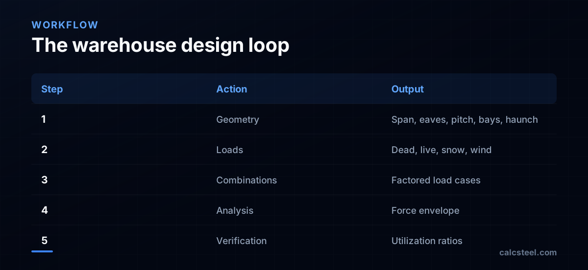
This is the direct, click-by-click answer to how to design a simple steel warehouse. We will take one concrete building all the way through: a 30 m clear span, 6 m eaves height, 10 degree roof pitch, with frames at 8 m bays - a typical single-span shed.
- 1. Model the geometry. Open the editor and draw the two columns and two rafters of the portal. Set span 30 m, eaves 6 m, apex from the 10 degree pitch. Add an eaves haunch where the bending moment peaks - SteelConstruction.info notes the haunch length is commonly about 10% of the span, so roughly 3 m here.
- 2. Apply loads. Add roof dead load (cladding and services, often 0.1-0.25 kN/m2), imposed/roof live load, snow where relevant, and wind pressures and uplift on roof and walls.
- 3. Build combinations. Let the engine factor and combine the load cases for your code, then take the envelope - the worst force in each member across every combination.
- 4. Pick and verify a section. Choose a trial UB/W/IPE section from the 1,140+ profile library, run the check, and read the utilization ratio. If it is above 1.0 the section fails; if it is well below, you are over-designed and can go lighter.
The next sections walk each step in detail, then place CalcSteel against the desktop tools. First, the background that explains why this frame, and why this loop, is the same everywhere.
The frame that eats half the steel
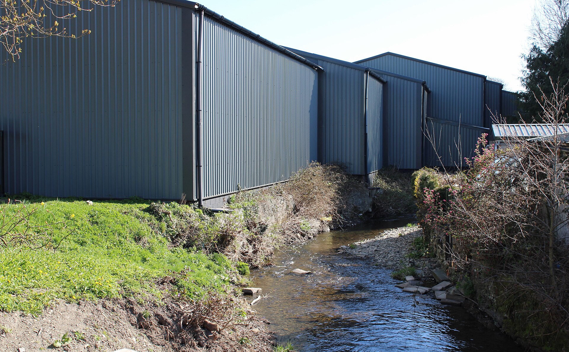
Walk past any industrial park and the silhouette repeats: a long, low building with a gently pitched roof and no internal columns. That is the single-span portal frame, the workhorse of warehouse, distribution-centre and factory construction. SteelConstruction.info reports that portal frames account for around 50% of all constructional steel used in the UK.
The appeal is structural. A rigid frame of two columns and two rafters, joined by moment-resisting connections at the eaves and apex, encloses a large column-free volume with very little steel. SteelConstruction.info gives the practical envelope: spans most efficient from about 25 m to 35 m, with frames spaced 6 to 8 m apart. Those are the starting numbers for almost every warehouse you will model - and for the 30 m / 8 m example above.
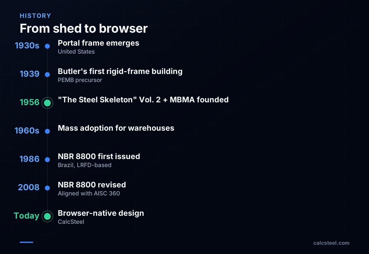
The form is usually traced to the United States in the 1930s: simple load path, repetitive fabrication, fast erection. Butler Manufacturing built its first rigid-frame design in 1939, an early step toward the pre-engineered metal building (PEMB) sector, and in 1956 thirteen companies, including Butler, Armco and Stran-Steel, founded the Metal Building Manufacturers Association (MBMA). Over the following decades the clear-span shed went from custom engineering to a catalog product.
Plastic theory: the idea that made the portal frame cheap
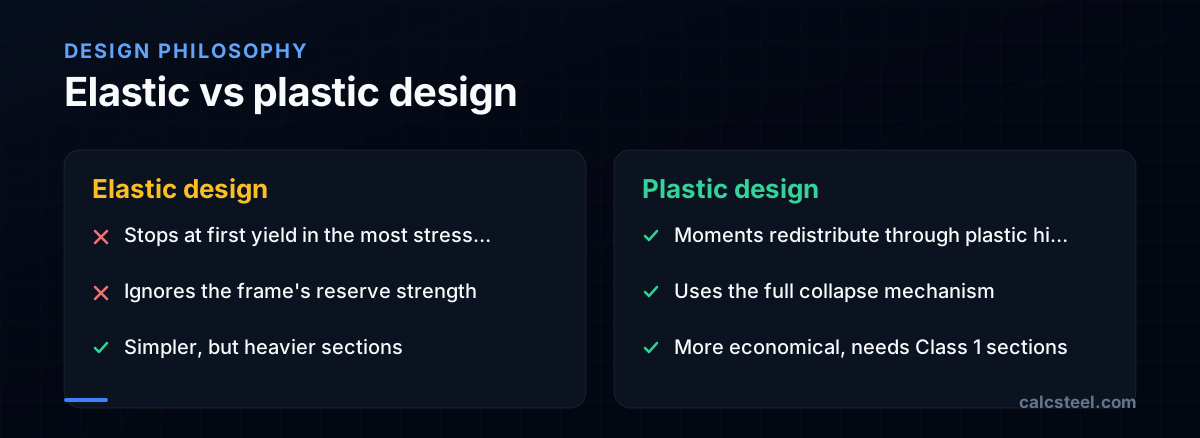
What made the warehouse frame economical was not its geometry but a change in how engineers thought about failure. Classical elastic design stops at the moment the most stressed fibre reaches yield, even though a ductile steel frame is nowhere near collapse at that point. Plastic theory recognises that a redundant frame keeps carrying load by forming plastic hinges, redistributing bending moments until enough hinges create a collapse mechanism.
This was the work of Sir John Baker and his colleagues at the University of Cambridge from the 1930s through the 1950s. According to Wikipedia, plastic theory was used to design the department's own Baker Building at Cambridge - reportedly the first building in the world designed by this method. The definitive text, The Steel Skeleton, Volume 2: Plastic Behaviour and Design by Baker, Horne and Heyman, was published by Cambridge University Press in 1956.
Modern codes still embed this thinking. As SteelConstruction.info sets out, plastic analysis of a portal frame is permitted only where members at rotating hinge locations are Class 1 (plastic) sections, capable of the rotation a hinge demands, with Class 2 compact sections elsewhere. That single detailing rule is why the haunch and section classification matter so much in step 4.
Loads and combinations: building the force envelope
The historical philosophy becomes a concrete numeric step. Once the 30 m frame is drawn, you apply the loads and let CalcSteel assemble the combinations:
- Dead (D). Self-weight of the frame plus roof cladding and services, often 0.1-0.25 kN/m2.
- Live / roof live (L). Imposed roof load and maintenance access.
- Snow (S). Balanced and, where relevant, drifted snow.
- Wind (W). Pressure and suction on walls and roof; on a low, light shed the wind uplift case often governs the design because it reverses the gravity moments.
The engine then factors and combines these. The combinations below are ASCE 7-16 (American practice) - shown so the logic is concrete, not because they are universal. Using a one-line key (D = dead, L = live, S = snow, W = wind), the strength cases include 1.2D + 1.6L + 0.5S, the wind-on-gravity case 1.2D + 1.0W + L + 0.5S, and the critical uplift case 0.9D + 1.0W. CalcSteel solves the frame under each, then keeps the envelope: the worst axial, shear and moment in every member across all cases.
If you are on NBR 8800 or Eurocode 3, do not copy these factors. NBR 8800 and EN 1993 use different partial factors and combination rules, and CalcSteel generates the correct set automatically when you select that code. The five-step loop is identical; only the numbers change.
Reading the verification results: what success looks like
This is the part a how-to usually skips. After the envelope is built, you pick a trial section and CalcSteel returns a verification per member and per limit state, expressed as a utilization (demand/capacity) ratio. For our 30 m frame, you might start the rafter as a UB 533x210 (or an IPE 550 / W21 equivalent) and the column heavier, then read back values such as a combined bending-plus-axial utilization of, for example, 0.86 under the governing uplift combination - the worst case the envelope captured.
What to look for in the results:
- Ratio above 1.0: the section fails that check - go heavier or deepen the haunch.
- Ratio well below 1.0 (say under 0.6): over-designed - try a lighter profile to save steel and cost.
- Governing case and member: the report flags which combination and which member drives the result, so you know whether wind uplift, gravity or stability controls.
- Stability and connections: member buckling, frame stability, and the eaves/apex moment connections each get their own check.
Iterate steps 4-5 until the heaviest-loaded member sits comfortably below 1.0. That converged set of sections, with documented utilizations, is the deliverable - the same outcome an engineer would hand-calculate, produced in minutes in the browser.
CalcSteel vs the alternatives: an honest verdict
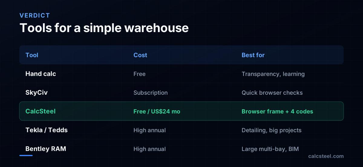
CalcSteel is one option, not the only one. For a simple clear-span shed, the realistic choices are hand calculation, a browser tool like SkyCiv, or a desktop suite such as Tekla Structural Designer / Tedds or Bentley RAM. They differ mainly on cost, install footprint and how far they scale beyond the simple case.
- Hand calculation is free and transparent but slow and error-prone once you build the full combination matrix and envelope.
- Desktop suites (Tekla, RAM) are the industrial standard - deep detailing, crane and seismic modules, BIM integration - but carry four- to five-figure annual licences and a steep learning curve, which is heavy for a single shed.
- Browser tools (SkyCiv, CalcSteel) trade some of that depth for instant access and lower cost. CalcSteel is browser-native (React/TypeScript front end, Python finite-element backend), has 1,140+ profiles, checks against NBR 8800, AISC 360, Eurocode 3 and IS 800, and runs the warehouse loop on a free plan, with Pro at US$24/month billed annually for heavier exports.
Be honest about scope: very large multi-bay buildings with cranes, fatigue, or complex seismic demands still warrant a specialist and a full desktop suite. But for the everyday clear-span shed - that decades-old portal frame, plastic theory and all - you can model, combine, and code-check the frame for free. If your code is NBR 8800 or Eurocode 3, CalcSteel applies your factors directly rather than the American example shown above. Open the editor and build the 30 m frame the way Baker's generation would recognise, just much faster.
Sources
- 1.Portal frames - SteelConstruction.info
- 2.John Baker, Baron Baker - Wikipedia
- 3.The Steel Skeleton Vol. 2: Plastic Behaviour and Design (Baker, Horne & Heyman, 1956) - Cambridge University Press
- 4.ASCE 7-16 LRFD Load Combinations - SkyCiv
- 5.History of Butler Manufacturing Company - FundingUniverse
- 6.Metal Building Manufacturers Association - Wikipedia
- 7.On the revision of the Brazilian standard NBR 8800 - SciELO Brazil
- 8.Image: Peter Evans — CC BY-SA 2.0 (Wikimedia Commons)
Try CalcSteel for free
Model, analyze and design steel structures in your browser. No install, no signup.
Open the 3D editor